| Last Modified: 01-30-2024 | 6.11:8.1.0 | Doc ID: RM100000001HD5B |
| Model Year Start: 2019 | Model: RAV4 | Prod Date Range: [02/2019 - 10/2022] |
| Title: POWER ASSIST SYSTEMS: POWER STEERING SYSTEM (for Type B): EPS Warning Light Circuit; 2019 - 2022 MY RAV4 RAV4 HV [02/2019 - 10/2022] | ||
|
EPS Warning Light Circuit |
DESCRIPTION
Perform the following troubleshooting procedure when the EPS warning light remains on after the engine is started, but no DTCs are stored.
HINT:
- If the power steering ECU (rack and pinion power steering gear assembly) detects a malfunction in the power source voltage input (IG) circuit, the EPS warning light illuminates.
- If the power steering ECU (rack and pinion power steering gear assembly) detects a drop in the power voltage input (IG and PIG) circuit, the force required to turn the steering wheel may increase, the EPS warning light turns on in order to warn the driver.
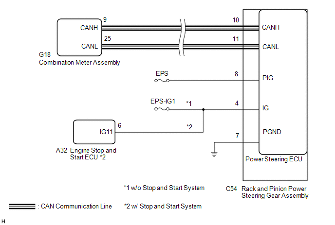
WIRING DIAGRAM
CAUTION / NOTICE / HINT
NOTICE:
-
If the rack and pinion power steering gear assembly has been replaced, perform assist map writing and torque sensor zero point calibration.
Click here
![2019 - 2024 MY RAV4 RAV4 HV [02/2019 - ]; POWER ASSIST SYSTEMS: POWER STEERING SYSTEM (for Type B): CALIBRATION](/t3Portal/stylegraphics/info.gif)
- Inspect the fuses for circuits related to this system before performing the following procedure.
PROCEDURE
|
1. |
CHECK ASSIST LIMIT RECORD |
(a) Using the Techstream, read the Data List item "Assist Limit Record 1".
Chassis > EMPS > Data List
|
Tester Display |
Measurement Item |
Range |
Normal Condition |
Diagnostic Note |
|---|---|---|---|---|
|
Assist Limit Record 1 |
Information of assist limit that was used in the past or is currently in use (latest history) |
Unrec, Mtr Overheat, Pow Vol Low, Pow Vol Low Prevent, Eng Stall, Ready OFF, Mtr Overload, Vhcl Spd Sig Malf, Batt Vol Keep |
- |
- |
Chassis > EMPS > Data List
|
Tester Display |
|---|
|
Assist Limit Record 1 |
HINT:
For the Data List item "Assist Limit Record 1", each item in the Range is described below.
|
Range |
Description |
|---|---|
|
Mtr Overheat |
When the vehicle is stopped or traveling at low speed, and steering operations are performed repeatedly or the steering wheel is turned all the way to the side and held there for a long time, assist may be limited in order to prevent overheating of the power steering motor assembly and power steering ECU assembly. After 10 minutes elapse with the engine stopped and no steering operations being performed, the system will return to normal. After recovering from the overheated condition, assist can be performed as usual. |
|
Pow Vol Low |
When insufficient battery charge, or battery degradation etc. causes the voltage to temporarily decrease, assist may be stopped. After the battery condition returns to normal, assist can be performed as usual. |
|
Pow Vol Low Prevent |
When insufficient battery charge, or battery degradation etc. causes the voltage to temporarily decrease, assist may be limited. After the battery condition returns to normal, assist can be performed as usual. |
|
Eng Stall |
When the engine stalls, battery charge becomes insufficient, so assist is stopped. After recovering from the engine stall, assist can be performed as usual. |
|
Ready OFF |
After Ready ON, if a malfunction in the HV system etc. causes a return to Ready OFF, the HV battery charge becomes insufficient, so assist is stopped. After returning to Ready ON state, assist can be performed as usual. |
|
Mtr Overload |
When the steering wheel cannot turn, such as when a road wheel is against a curb, if the driver continues to apply force to the steering wheel, current to the motor may be limited to prevent overheating. When the steering wheel is returned to a neutral position, assist can be performed as usual. |
|
DC-DC Malf |
If there is a malfunction in the DC-DC converter, etc., assist may be limited. After the DC-DC converter returns to normal, assist can be performed as usual. |
|
Vhcl Spd Sig Malf |
If the vehicle speed signal is abnormal due to a wheel speed sensor malfunction, etc., assist may be limited. |
|
Batt Vol Keep |
When insufficient battery charge, or battery degradation etc. causes the voltage to temporarily decrease, assist may be limited. After the battery condition returns to normal, assist can be performed as usual. |
(b) Based on the "Assist Limit Record 1" information, the following Data List items and the information from the customer interview, explain the situation to the customer.
Chassis > EMPS > Data List
|
Tester Display |
Measurement Item |
Range |
Normal Condition |
Diagnostic Note |
|---|---|---|---|---|
|
Record 1 Key Cycle |
Number of times that the ignition switch was turned to ON before Assist Limit Record 1 was stored |
Min.: 0 times Max.: 65535 times |
- |
- |
|
Record 1 Key Cycle Elapsed Time |
Period of time that elapsed since the ignition switch was turned to ON before Assist Limit Record 1 was stored |
Min.: 0.0 s Max.: 53687091.1 s |
- |
- |
Chassis > EMPS > Data List
|
Tester Display |
|---|
|
Record 1 Key Cycle |
|
Record 1 Key Cycle Elapsed Time |
|
Result |
Proceed to |
|---|---|
|
"Unrec" is displayed |
A |
|
Other than Unrec is displayed |
B |
HINT:
If it is necessary to investigate further into the past, check the "Assist Limit Record 2" and "Assist Limit Record 3" information in the same way as "Assist Limit Record 1".
| B |

|
EXPLAIN THE CHECKED "ASSIST LIMIT RECORD 1" TO THE CUSTOMER, CROSS-CHECKING THE DATA LIST ITEMS WITH THE INFORMATION FROM THE CUSTOMER INTERVIEW. |
|

|
2. |
CHECK HARNESS AND CONNECTOR |
(a) Jiggle the rack and pinion power steering gear assembly connectors and wire harness up and down, and left and right to check the illumination condition of the EPS warning light in the combination meter assembly.
OK:
The EPS warning light illumination condition does not change.
HINT:
for HV Model:
When the EPS warning light is operating properly, it illuminates when the power switch is turned on (IG) and turns off when the hybrid system is started.
for Gasoline Model:
When the EPS warning light is operating properly, it illuminates when the ignition switch is turned ON and turns off when the engine is started.
| NG |
|
REPAIR OR REPLACE HARNESS OR CONNECTOR |
|
|
3. |
CHECK CAN COMMUNICATION SYSTEM |
(a) Check for DTCs.
for Gasoline Model: Click here
for HV Model: Click here
|
Result |
Proceed to |
|---|---|
|
CAN communication system DTCs are not output. (w/ Stop and Start System) |
A |
|
CAN communication system DTCs are not output. (w/o Stop and Start System) |
B |
|
CAN communication system DTCs are output. |
C |
| B |
|
| C |
|
GO TO CAN COMMUNICATION SYSTEM for Gasoline Model: Click here
for HV Model: Click here
|
|
|
4. |
CHECK HARNESS AND CONNECTOR (IG POWER SUPPLY - GROUND) |
(a) Disconnect the C54 rack and pinion power steering gear assembly connector.

|
*a |
Front view of wire harness connector (to Rack and Pinion Power Steering Gear Assembly) |
- |
- |
(b) Measure the voltage according to the value(s) in the table below.
Standard Voltage:
|
Tester Connection |
Condition |
Specified Condition |
|---|---|---|
|
C54-8 (PIG) - Body ground |
Ignition switch ON |
9 to 16 V |
(c) Measure the resistance according to the value(s) in the table below.
Standard Resistance:
|
Tester Connection |
Condition |
Specified Condition |
|---|---|---|
|
C54-7 (PGND) - Body ground |
Always |
Below 1 Ω |
| NG |
|
REPAIR OR REPLACE HARNESS OR CONNECTOR |
|
|
5. |
CHECK HARNESS AND CONNECTOR (IG POWER SUPPLY) |
(a) Disconnect the C54 rack and pinion power steering gear assembly connector.

|
*a |
Front view of wire harness connector (to Rack and Pinion Power Steering Gear Assembly) |
- |
- |
(b) Measure the voltage according to the value(s) in the table below.
Standard Voltage:
|
Tester Connection |
Condition |
Specified Condition |
|---|---|---|
|
C54-4 (IG) - Body ground |
Ignition switch ON |
8 to 16 V |
| NG |
|
GO TO STOP AND START SYSTEM (BACKUP BOOST CONVERTER CIRCUIT)
|
|
|
6. |
INSPECT COMBINATION METER ASSEMBLY |
(a) Connect the C54 rack and pinion power steering gear assembly connector.
(b) Perform the Active Test of the combination meter assembly using the Techstream.
Body Electrical > Combination Meter > Active Test
|
Tester Display |
|---|
|
Indicat. EPS |
(c) Check the combination meter assembly.
OK:
The EPS warning light turns on or off in accordance with the Techstream operation.
| OK |
|
REPLACE RACK AND PINION POWER STEERING GEAR ASSEMBLY
|
| NG |
|
|
7. |
CHECK HARNESS AND CONNECTOR (IG POWER SUPPLY - GROUND) |
(a) Disconnect the C54 rack and pinion power steering gear assembly connector.

|
*a |
Front view of wire harness connector (to Rack and Pinion Power Steering Gear Assembly) |
- |
- |
(b) Measure the voltage according to the value(s) in the table below.
Standard Voltage:
|
Tester Connection |
Condition |
Specified Condition |
|---|---|---|
|
C54-4 (IG) - Body ground |
Ignition switch ON |
8 to 16 V |
|
C54-8 (PIG) - Body ground |
Ignition switch ON |
9 to 16 V |
(c) Measure the resistance according to the value(s) in the table below.
Standard Resistance:
|
Tester Connection |
Condition |
Specified Condition |
|---|---|---|
|
C54-7 (PGND) - Body ground |
Always |
Below 1 Ω |
| NG |
|
REPAIR OR REPLACE HARNESS OR CONNECTOR |
|
|
8. |
INSPECT COMBINATION METER ASSEMBLY |
(a) Connect the C54 rack and pinion power steering gear assembly connector.
(b) Perform the Active Test of the combination meter assembly using the Techstream.
Body Electrical > Combination Meter > Active Test
|
Tester Display |
|---|
|
EPS Warning |
(c) Check the combination meter assembly.
OK:
The EPS warning light turns on or off in accordance with the Techstream operation.
| OK |
|
REPLACE RACK AND PINION POWER STEERING GEAR ASSEMBLY
|
| NG |
|
|
|
|