| Last Modified: 01-30-2024 | 6.11:8.1.0 | Doc ID: RM100000001HCAS |
| Model Year Start: 2019 | Model: RAV4 HV | Prod Date Range: [02/2019 - 08/2020] |
| Title: P710 (HYBRID TRANSMISSION / TRANSAXLE): OIL COOLER: INSTALLATION; 2019 - 2020 MY RAV4 HV [02/2019 - 08/2020] | ||
INSTALLATION
PROCEDURE
1. INSTALL NO. 1 MOTOR COOLING HOSE
HINT:
Perform this procedure only when replacement of the motor cooling cooler is necessary.
(a) Coat the pipe of the motor cooling cooler with a small amount of ATF as shown in the illustration.
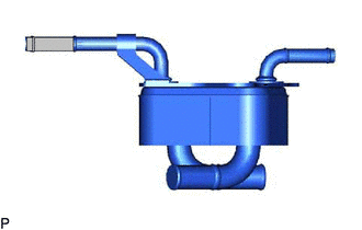

|
ATF Application Area |
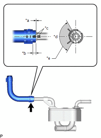
(b) Install the No. 1 motor cooling hose to the motor cooling cooler, and slide the clip to secure it.
|
*a |
0 to 3 mm (0 to 0.118 in.) |
|
*b |
2 to 7 mm (0.0787 to 0.276 in.) |
|
*c |
Paint Mark |
|
*d |
Center of Paint Mark |
|
*e |
120° |

|
Claw of Clip Location |
NOTICE:
- Be careful not to deform the motor cooling cooler.
- Make sure to align the paint mark of the No. 1 motor cooling hose with the paint mark of the motor cooling cooler.
- Make sure that the claws of the clip are positioned within the area shown in the illustration.
2. INSTALL NO. 2 MOTOR COOLING HOSE
HINT:
Perform this procedure only when replacement of the motor cooling cooler is necessary.
(a) Coat the pipe of the motor cooling cooler with a small amount of ATF as shown in the illustration.
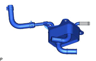

|
ATF Application Area |
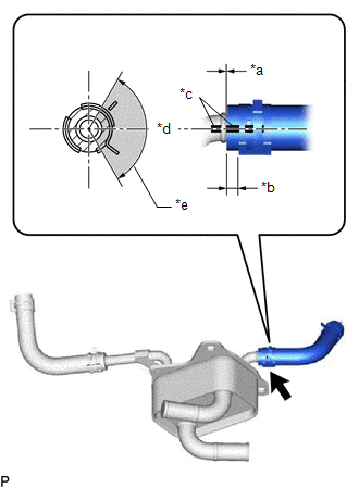
(b) Install the No. 2 motor cooling hose to the motor cooling cooler, and slide the clip to secure it.
|
*a |
0 to 3 mm (0 to 0.118 in.) |
|
*b |
2 to 7 mm (0.0787 to 0.276 in.) |
|
*c |
Paint Mark |
|
*d |
Center of Paint Mark |
|
*e |
120° |

|
Claw of Clip Location |
NOTICE:
- Be careful not to deform the motor cooling cooler.
- Make sure to align the paint mark of the No. 2 motor cooling hose with the paint mark of the motor cooling cooler.
- Make sure that the claws of the clip are positioned within the area shown in the illustration.
3. INSTALL NO. 2 MOTOR COOLING PIPE
(a) Install the No. 2 motor cooling pipe to the No. 2 motor cooling hose, and slide the clip to secure it.
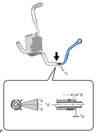
|
*a |
0 to 3 mm (0 to 0.118 in.) |
|
*b |
2 to 7 mm (0.0787 to 0.276 in.) |
|
*c |
Paint Mark |
|
*d |
Center of Paint Mark |
|
*e |
15° |

|
Center of Clip Location |
NOTICE:
- Make sure to align the paint mark of the No. 2 motor cooling pipe with the paint mark of the No. 2 motor cooling hose.
- Make sure that the center of the clip (between the claws of the clip) is within 15° of the center of the paint mark as shown in the illustration.
4. INSTALL MOTOR COOLING COOLER
(a) Connect the No. 1 motor cooling hose to the transaxle housing tube connector, and slide the clip to secure it.
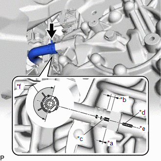
|
*a |
0 to 3 mm (0 to 0.118 in.) |
|
*b |
2 to 7 mm (0.0787 to 0.276 in.) |
|
*c |
Paint Mark |
|
*d |
Rib |
|
*e |
Center of Rib |
|
*f |
180° |

|
Claw of Clip Location |
NOTICE:
- Make sure to align the paint mark of the No. 1 motor cooling hose with the rib of the hybrid vehicle transaxle assembly.
- Make sure that the claws of the clip are within the location shown in the illustration.
|
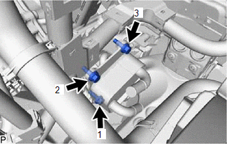
(b) Temporarily install the motor cooling cooler to the No. 1 transmission control cable bracket with the 3 bolts. |
|
(c) Tighten the 3 bolts in the order shown in the illustration.
Torque:
11.5 N·m {117 kgf·cm, 8 ft·lbf}
|
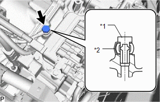
(d) Temporarily install the No. 2 motor cooling pipe to the hybrid vehicle transaxle assembly with the oil cooler union bolt and a new gasket. |
|
|
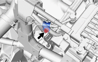
(e) Install the No. 2 motor cooling pipe to the hose bracket with the bolt and No. 1 oil cooler tube clamp. Torque: 11.5 N·m {117 kgf·cm, 8 ft·lbf} |
|
|
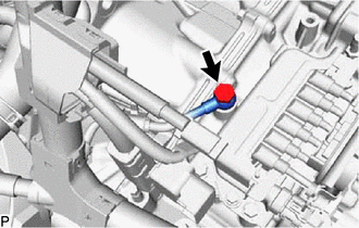
(f) Tighten the oil cooler union bolt. Torque: 35 N·m {357 kgf·cm, 26 ft·lbf} |
|
5. CONNECT NO. 5 INVERTER COOLING HOSE
6. INSTALL NO. 1 INVERTER COOLING HOSE
(a) Install the No. 1 inverter cooling hose to the motor cooling cooler, and slide the clip to secure it.
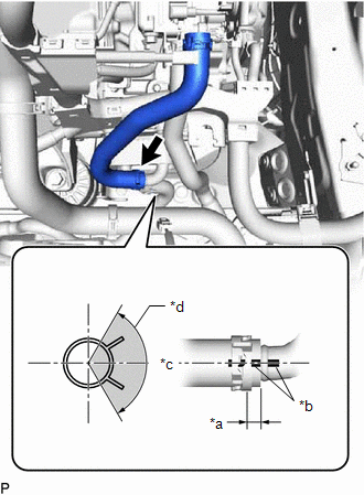
|
*a |
2 to 7 mm (0.0787 to 0.276 in.) |
|
*b |
Paint Mark |
|
*c |
Center of Paint Mark |
|
*d |
120° |

|
Claw of Clip Location |
NOTICE:
- Be careful not to deform the motor cooling cooler.
- Make sure to align the paint mark of the No. 1 inverter cooling hose with the paint mark of the motor cooling cooler.
- Make sure that the claws of the clip are positioned within the area shown in the illustration.
7. INSTALL INVERTER WITH CONVERTER ASSEMBLY
8. INSPECT HYBRID TRANSAXLE FLUID
9. INSPECT FOR HYBRID TRANSAXLE FLUID LEAK
10. INSTALL FRONT FENDER APRON SEAL LH
11. INSTALL NO. 2 ENGINE UNDER COVER ASSEMBLY
12. INSTALL NO. 1 ENGINE UNDER COVER
13. INSTALL FRONT FENDER FRONT SPLASH SHIELD RH
14. INSTALL FRONT FENDER FRONT SPLASH SHIELD LH
|
|
|
![2019 - 2020 MY RAV4 HV [02/2019 - 08/2020]; A25A-FXS (ENGINE MECHANICAL): ENGINE ASSEMBLY: INSTALLATION+](/t3Portal/stylegraphics/info.gif)