| Last Modified: 11-18-2025 | 6.11:8.1.0 | Doc ID: RM100000001H3KQ |
| Model Year Start: 2019 | Model: RAV4 HV | Prod Date Range: [02/2019 - ] |
| Title: HYBRID / BATTERY CONTROL: HYBRID CONTROL SYSTEM (for AWD with NICKEL METAL HYDRIDE BATTERY): Transmission Control Switch Circuit; 2019 - 2025 MY RAV4 HV [02/2019 - ] | ||
|
Transmission Control Switch Circuit |
DESCRIPTION
When the shift lever is in S, different ranges can be chosen using the floor shift sequential gate.
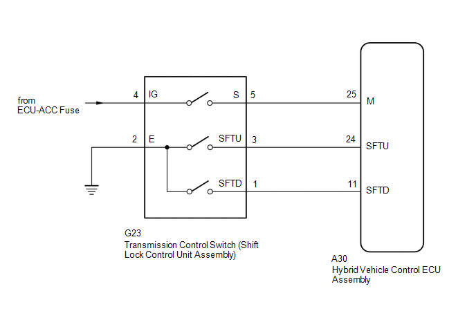
WIRING DIAGRAM
PROCEDURE
PROCEDURE
|
1. |
READ VALUE USING TECHSTREAM (SPORTS SHIFT POSITION) |
(a) Connect the Techstream to the DLC3.
(b) Turn the ignition switch to ON.
(c) Enter the following menus: Powertrain / Hybrid Control / Data List / Sports Shift Position.
Powertrain > Hybrid Control > Data List
|
Tester Display |
|---|
|
Sports Shift Position |
(d) Read the value displayed on the Techstream.
Powertrain > Hybrid Control > Data List
|
Tester Display |
Measurement Item |
Range |
Normal Condition |
|---|---|---|---|
|
Sports Shift Position |
Sports shift position |
0 to 255 |
Shift lever in S, "+" or "-": 1 to 6 Shift lever in any position other than S, "+" and "-": 255 |
|
Result |
Proceed to |
|---|---|
|
The Techstream display changes according to the shift lever operation. |
A |
|
The Techstream display does not change according to the shift lever operation. |
B |
(e) Turn the ignition switch off.
| B |

|
|

|
2. |
READ VALUE USING TECHSTREAM (SPORTS SHIFT UP SIGNAL, SPORTS SHIFT DOWN SIGNAL) |
(a) Connect the Techstream to the DLC3.
(b) Turn the ignition switch to ON.
(c) Enter the following menus: Powertrain / Hybrid Control / Data List / Sports Shift UP Signal, Sports Shift DOWN Signal.
Powertrain > Hybrid Control > Data List
|
Tester Display |
|---|
|
Sports Shift UP Signal |
|
Sports Shift DOWN Signal |
(d) Read the value displayed on the Techstream.
Powertrain > Hybrid Control > Data List
|
Tester Display |
Measurement Item |
Range |
Normal Condition |
|---|---|---|---|
|
Sports Shift UP Signal |
Operation of "+" transmission control switch. |
ON or OFF |
Shift lever held in "+" operated: ON Shift lever in S: OFF |
|
Sports Shift DOWN Signal |
Operation of "-" transmission control switch. |
ON or OFF |
Shift lever held in "-" operated: ON Shift lever in S: OFF |
|
Result |
Proceed to |
|---|---|
|
The Techstream display changes according to the transmission control switch (shift lock control unit assembly) operation. |
A |
|
The Techstream display does not change according to the transmission control switch (shift lock control unit assembly) operation. |
B |
(e) Turn the ignition switch off.
| B |
|
|
|
3. |
CHECK FOR INTERMITTENT PROBLEMS |
Click here
![2019 - 2025 MY RAV4 HV [02/2019 - ]; HYBRID / BATTERY CONTROL: HYBRID CONTROL SYSTEM (for AWD with NICKEL METAL HYDRIDE BATTERY): CHECK FOR INTERMITTENT PROBLEMS](/t3Portal/stylegraphics/info.gif)
| OK |
|
REPLACE HYBRID VEHICLE CONTROL ECU ASSEMBLY Click here
|
| NG |
|
REPAIR OR REPLACE MALFUNCTIONING PARTS, COMPONENT AND AREA |
|
4. |
CHECK HARNESS AND CONNECTOR (POWER SOURCE CIRCUIT) |
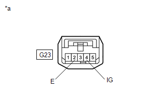
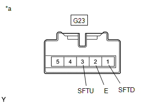
(a) Disconnect the G23 transmission control switch (shift lock control unit assembly) connector.
(b) Turn the ignition switch to ON.
|
(c) Measure the voltage according to the value(s) in the table below. Standard Voltage:
|
|
(d) Turn the ignition switch off.
(e) Measure the voltage according to the value(s) in the table below.
Standard Voltage:
|
Tester Connection |
Condition |
Specified Condition |
|---|---|---|
|
G23-4 (IG) - Body ground |
Ignition switch off |
Below 1 V |
(f) Measure the resistance according to the value(s) in the table below.
Standard Resistance:
|
Tester Connection |
Condition |
Specified Condition |
|---|---|---|
|
G23-2 (E) - Body ground |
Ignition switch off |
Below 1 Ω |
(g) Reconnect the G23 transmission control switch (shift lock control unit assembly) connector.
| NG |
|
CHECK POWER SOURCE CIRCUIT |
|
|
5. |
INSPECT TRANSMISSION CONTROL SWITCH (SHIFT LOCK CONTROL UNIT ASSEMBLY) |
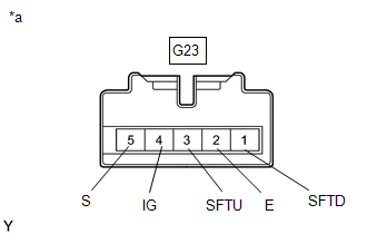
(a) Disconnect the G23 transmission control switch (shift lock control unit assembly) connector.
|
(b) Measure the resistance according to the value(s) in the table below when the shift lever is moved to each position. Standard Resistance:
|
|
(c) Reconnect the G23 transmission control switch (shift lock control unit assembly) connector.
| NG |
|
|
|
6. |
CHECK HARNESS AND CONNECTOR (HYBRID VEHICLE CONTROL ECU ASSEMBLY - TRANSMISSION CONTROL SWITCH (SHIFT LOCK CONTROL UNIT ASSEMBLY)) |
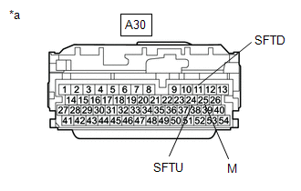
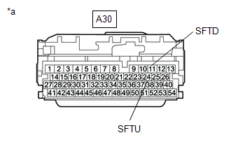
(a) Disconnect the A30 hybrid vehicle control ECU assembly connector.
(b) Turn the ignition switch to ON.
|
(c) Measure the voltage according to the value(s) in the table below when the shift lever is moved to each position. Standard Voltage:
NOTICE: If the ignition switch is turned to ON with the hybrid vehicle control ECU assembly connector disconnected, other DTCs will be stored. After performing the inspection, clear the DTCs. |
|
(d) Turn the ignition switch off.
(e) Measure the resistance according to the value(s) in the table below when the shift lever is moved to each position.
Standard Resistance:
|
Tester Connection |
Condition |
Specified Condition |
|---|---|---|
|
A30-24 (SFTU) - Body ground |
Shift lever held in "+" |
Below 1 Ω |
|
A30-24 (SFTU) - Body ground |
Shift lever in S |
10 kΩ or higher |
|
A30-11 (SFTD) - Body ground |
Shift lever held in "-" |
Below 1 Ω |
|
A30-11 (SFTD) - Body ground |
Shift lever in S |
10 kΩ or higher |
(f) Reconnect the A30 hybrid vehicle control ECU assembly connector.
| OK |
|
REPLACE HYBRID VEHICLE CONTROL ECU ASSEMBLY Click here
|
| NG |
|
REPAIR OR REPLACE HARNESS OR CONNECTOR |
|
7. |
INSPECT TRANSMISSION CONTROL SWITCH (SHIFT LOCK CONTROL UNIT ASSEMBLY) |
(a) Disconnect the G23 transmission control switch (shift lock control unit assembly) connector.
|
(b) Measure the resistance according to the value(s) in the table below when the shift lever is moved to each position. Standard Resistance:
|
|
(c) Reconnect the G23 transmission control switch (shift lock control unit assembly) connector.
| NG |
|
|
|
8. |
CHECK HARNESS AND CONNECTOR (TRANSMISSION CONTROL SWITCH (SHIFT LOCK CONTROL UNIT ASSEMBLY) - HYBRID VEHICLE CONTROL ECU ASSEMBLY) |
(a) Disconnect the A30 hybrid vehicle control ECU assembly connector.
|
(b) Measure the resistance according to the value(s) in the table below when the shift lever is moved to each position. Standard Resistance:
|
|
(c) Reconnect the A30 hybrid vehicle control ECU assembly connector.
| OK |
|
REPLACE HYBRID VEHICLE CONTROL ECU ASSEMBLY Click here
|
| NG |
|
REPAIR OR REPLACE HARNESS OR CONNECTOR |
|
|
|