- Inverter Water Pump Revolution
- Inverter Water Pump Duty Ratio
- Ready Signal
| Last Modified: 01-30-2024 | 6.11:8.1.0 | Doc ID: RM100000001H3KI |
| Model Year Start: 2019 | Model: RAV4 HV | Prod Date Range: [02/2019 - ] |
| Title: HYBRID / BATTERY CONTROL: HYBRID CONTROL SYSTEM (for AWD with NICKEL METAL HYDRIDE BATTERY): P314A31; Motor Electronics Coolant Pump "A" No Signal; 2019 - 2024 MY RAV4 HV [02/2019 - ] | ||
|
DTC |
P314A31 |
Motor Electronics Coolant Pump "A" No Signal |
DESCRIPTION
Refer to the description for DTC P0C7396.
Click here
![2019 - 2024 MY RAV4 HV [02/2019 - ]; HYBRID / BATTERY CONTROL: HYBRID CONTROL SYSTEM (for AWD with NICKEL METAL HYDRIDE BATTERY): P0C7396; Motor Electronics Coolant Pump "A" Component Internal Failure+](/t3Portal/stylegraphics/info.gif)
The inverter water pump assembly sends the inverter water pump speed (measured value) signal to the hybrid vehicle control ECU assembly.
|
DTC No. |
Detection Item |
DTC Detection Condition |
Trouble Area |
MIL |
Warning Indicate |
|---|---|---|---|---|---|
|
P314A31 |
Motor Electronics Coolant Pump "A" No Signal |
The inverter water pump speed signal is not sent to the hybrid vehicle control ECU assembly when the ignition switch is turned to ON (READY).* (1 trip detection logic) |
|
Comes on |
Master Warning: Comes on |
*: Any of the following conditions is met.
- A malfunction (open, short to +B or short to ground) in the speed signal line from the inverter water pump assembly to the hybrid vehicle control ECU assembly is detected.
- A malfunction in the +B line is detected.
- A malfunction in the inverter water pump assembly power source circuit is detected.
- A malfunction in hybrid vehicle control ECU assembly power source circuit is detected.
Related Data List
|
DTC No. |
Data List |
|---|---|
|
P314A31 |
|
Related Active Test
|
DTC No. |
Active Test |
|---|---|
|
P314A31 |
Activate the Inverter Water Pump |
MONITOR DESCRIPTION
The hybrid vehicle control ECU assembly monitors the speed of the inverter water pump assembly. If the inverter water pump speed signal is not sent to the hybrid vehicle control ECU assembly, the hybrid vehicle control ECU assembly will illuminate the MIL and store a DTC.
MONITOR STRATEGY
|
Related DTCs |
P314A (INF P314A31): Inverter water pump malfunction |
|
Required sensors/components |
Inverter Water Pump Assembly |
|
Frequency of operation |
Continuous |
|
Duration |
TMC's intellectual property |
|
MIL operation |
Immediately |
|
Sequence of operation |
None |
TYPICAL ENABLING CONDITIONS
|
The monitor will run whenever the following DTCs are not stored |
TMC's intellectual property |
|
Other conditions belong to TMC's intellectual property |
- |
TYPICAL MALFUNCTION THRESHOLDS
|
TMC's intellectual property |
- |
COMPONENT OPERATING RANGE
|
Hybrid vehicle control ECU assembly |
DTC P314A (INF P314A31) is not detected |
CONFIRMATION DRIVING PATTERN
HINT:
-
After repair has been completed, clear the DTC and then check that the vehicle has returned to normal by performing the following All Readiness check procedure.
Click here
-
When clearing the permanent DTCs, refer to the "CLEAR PERMANENT DTC" procedure.
Click here
- Connect the Techstream to the DLC3.
- Turn the ignition switch to ON and turn the Techstream on.
- Clear the DTCs (even if no DTCs are stored, perform the clear DTC procedure).
- Turn the ignition switch off and wait for 2 minutes or more.
- Turn the ignition switch to ON and turn the Techstream on.
-
Turn the ignition switch to ON (READY) and wait for 2 minutes or more. [*1]
HINT:
[*1]: Normal judgment procedure.
The normal judgment procedure is used to complete DTC judgment and also used when clearing permanent DTCs.
- Enter the following menus: Powertrain / Hybrid Control / Utility / All Readiness.
-
Check the DTC judgment result.
HINT:
- If the judgment result shows NORMAL, the system is normal.
- If the judgment result shows ABNORMAL, the system has a malfunction.
- If the judgment result shows INCOMPLETE, perform the normal judgment procedure again.
WIRING DIAGRAM
Refer to the wiring diagram for DTC P0C7396.
Click here
PROCEDURE
|
1. |
CLEAR DTC |
Click here
|

|
2. |
PERFORM ACTIVE TEST USING TECHSTREAM (ACTIVATE THE INVERTER WATER PUMP) |
NOTICE:
- Make sure that the HV coolant level is above the low line of the inverter reserve tank.
- Be sure to perform the inspection with the auxiliary battery voltage at 12 V or more.
HINT:
- When the auxiliary battery voltage is low, the inverter water pump with motor assembly may not operate.
- When the inverter water pump with motor assembly signal line (SWP - IWP) is open or its connection is faulty, the inverter water pump with motor assembly is operated forcibly.
(a) Connect the Techstream to the DLC3.
(b) Turn the ignition switch to ON.
(c) Enter the following menus: Powertrain / Hybrid Control / Active Test / Activate the Inverter Water Pump.
(d) Perform the "Activate the Inverter Water Pump" Active Test.
Powertrain > Hybrid Control > Active Test
|
Tester Display |
|---|
|
Activate the Inverter Water Pump |
(e) Touch the inverter water pump assembly and check that it is operating (vibrating).
OK:
The inverter water pump is operating (vibrating).
HINT:
Perform the Active Test with the inverter coolant temperature between -15 and 65°C (5 to 149°F).
(f) Turn the ignition switch off.
| NG |

|
|
|
3. |
CHECK CONNECTOR CONNECTION CONDITION (HYBRID VEHICLE CONTROL ECU ASSEMBLY CONNECTOR) |
Click here
| NG |
|
CONNECT SECURELY |
|
|
4. |
CHECK CONNECTOR CONNECTION CONDITION (INVERTER WATER PUMP ASSEMBLY CONNECTOR) |
Click here
| NG |
|
CONNECT SECURELY |
|
|
5. |
CHECK HARNESS AND CONNECTOR (HYBRID VEHICLE CONTROL ECU ASSEMBLY - INVERTER WATER PUMP ASSEMBLY) |
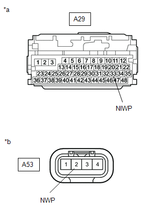
(a) Disconnect the A29 hybrid vehicle control ECU assembly connector.
(b) Disconnect the A53 inverter water pump assembly connector.
|
(c) Measure the resistance according to the value(s) in the table below. Standard Resistance (Check for Open):
Standard Resistance (Check for Short):
|
|
(d) Reconnect the A53 inverter water pump assembly connector.
(e) Reconnect the A29 hybrid vehicle control ECU assembly connector.
| NG |
|
REPAIR OR REPLACE HARNESS OR CONNECTOR |
|
|
6. |
CHECK HYBRID VEHICLE CONTROL ECU ASSEMBLY |
(a) Disconnect the A53 inverter water pump assembly connector.
(b) Turn the ignition switch to ON.
(c) Measure the voltage according to the value(s) in the table below.
|
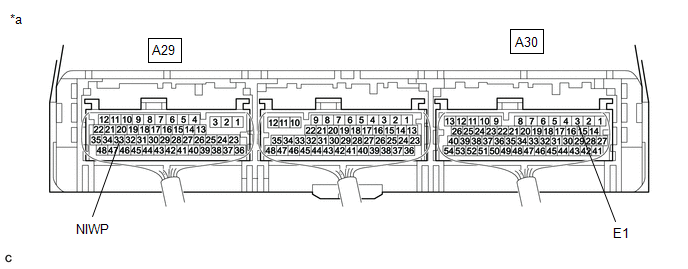
*a |
Component with harness connected (Hybrid Vehicle Control ECU Assembly) |
- |
- |
Standard Voltage:
|
Tester Connection |
Condition |
Specified Condition |
|---|---|---|
|
A29-33 (NIWP) - A30-3 (E1) |
Ignition switch ON |
11 to 14 V |
(d) Turn the ignition switch off.
(e) Reconnect the A53 inverter water pump assembly connector.
| NG |
|
REPLACE HYBRID VEHICLE CONTROL ECU ASSEMBLY
|
|
|
7. |
CLEAR DTC |
Click here
|
|
8. |
PERFORM ACTIVE TEST USING TECHSTREAM (ACTIVATE THE INVERTER WATER PUMP) |
NOTICE:
Be sure to perform the inspection with the auxiliary battery voltage at 12 V or more.
HINT:
When the auxiliary battery voltage is low, the inverter water pump assembly may not operate.
(a) Connect the Techstream to the DLC3.
(b) Turn the ignition switch to ON.
(c) Enter the following menus: Powertrain / Hybrid Control / Active Test / Activate the Inverter Water Pump.
(d) Perform the "Activate the Inverter Water Pump" Active Test.
Powertrain > Hybrid Control > Active Test
|
Tester Display |
|---|
|
Activate the Inverter Water Pump |
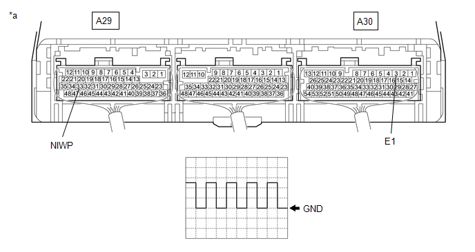
(e) Connect an oscilloscope between the hybrid vehicle control ECU assembly terminals specified in the table below, and measure the waveform.
|
*a |
Component with harness connected (Hybrid Vehicle Control ECU Assembly) |
- |
- |
|
Item |
Content |
|---|---|
|
Terminal |
A29-33 (NIWP) - A30-3 (E1) |
|
Equipment Setting |
5 V/DIV., 5 ms./DIV. |
|
Condition |
Ignition switch ON, during Active Test |
OK:
The period of the wavelength is 13 msec or less.
(f) Turn the ignition switch off.
| OK |
|
REPLACE HYBRID VEHICLE CONTROL ECU ASSEMBLY
|
| NG |
|
|
9. |
CHECK CONNECTOR CONNECTION CONDITION (INVERTER WATER PUMP ASSEMBLY CONNECTOR) |
Click here
| NG |
|
CONNECT SECURELY (INVERTER WATER PUMP ASSEMBLY CONNECTOR) |
|
|
10. |
CHECK INSTALLATION CONDITION (INV W/P RELAY) |
|
(a) Check installation condition of the INV W/P relay. OK: INV W/P relay is installed correctly. |
|
| NG |
|
|
|
11. |
CHECK HARNESS AND CONNECTOR (IGCT RELAY - INV W/P RELAY) |
|
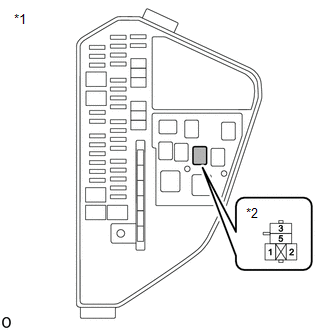
(a) Remove the IGCT relay from the No. 3 relay block and junction block assembly. |
|
|
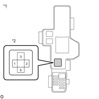
(b) Remove the INV W/P relay from the No. 1 engine room relay block and junction block assembly. |
|
|
(c) Measure the resistance according to the value(s) in the table below. Standard Resistance:
NOTICE: Do not apply excessive force when using the probes of the tester to perform the inspection. If excessive force is used, the terminals will be damaged. HINT:
|
|
(d) Install the IGCT relay and INV W/P relay.
| NG |
|
|
|
12. |
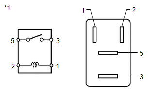
INSPECT RELAY (INV W/P) |
|
(a) Remove the INV W/P relay from the No. 1 engine room relay block and junction block assembly. |
|
|
(b) Measure the resistance according to the value(s) in the table below. Standard Resistance:
|
|
(c) Install the INV W/P relay.
| NG |
|
|
|
13. |
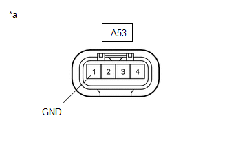
CHECK HARNESS AND CONNECTOR (INVERTER WATER PUMP ASSEMBLY - BODY GROUND) |
|
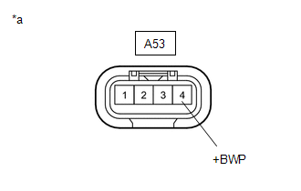
*a |
Front view of wire harness connector (to Inverter Water Pump Assembly) |
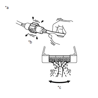
|
*a |
Example |
|
*b |
Shake Slightly |
|
*c |
Vibrate Slightly |
(a) Disconnect the A53 inverter water pump assembly connector.
(b) Measure the voltage according to the value(s) in the table below.
Standard Voltage:
|
Tester Connection |
Condition |
Specified Condition |
|---|---|---|
|
A53-4 (+BWP) - Body ground |
Ignition switch ON |
11 to 14 V |
NOTICE:
- If the ignition switch is turned to ON with the connectors disconnected, other DTCs will be stored. Be sure to clear the DTCs after the inspection.
- Do not apply excessive force when using the probes of the tester to perform the inspection. If excessive force is used, the terminals will be damaged.
HINT:
-
Connectors
Slightly shake the connector vertically and horizontally.
-
Wire Harness
Slightly shake the wire harness vertically and horizontally.
The connector joint and fulcrum of the vibration are the major areas that should be checked thoroughly.
-
No. 1 Engine Room Relay Block and Junction Block Assembly
Apply slight vibration with a finger to the No. 1 engine room relay block and junction block assembly and check whether a malfunction occurs.
-
INV W/P NO. 2 fuse
Apply slight vibration with a finger to the INV W/P NO. 2 fuse and check whether a malfunction occurs.
-
INV W/P Relay
Apply slight vibration with a finger to the INV W/P relay and check whether a malfunction occurs.
(c) Reconnect the A53 inverter water pump assembly connector.
| NG |
|
|
|
14. |
CHECK HARNESS AND CONNECTOR (INVERTER WATER PUMP ASSEMBLY - BODY GROUND) |
(a) Disconnect the A53 inverter water pump assembly connector.
|
(b) Measure the resistance according to the value(s) in the table below. Standard Resistance:
|
|
(c) Reconnect the A53 inverter water pump assembly connector.
| NG |
|
REPAIR OR REPLACE HARNESS OR CONNECTOR |
|
|
15. |
REPLACE INVERTER WATER PUMP ASSEMBLY |
Click here
|
|
16. |
ADD HV COOLANT AND PERFORM AIR BLEEDING |
(a) After replacing the inverter water pump with motor assembly, add HV coolant and perform air bleeding.
Click here
| NEXT |
|
END |
|
17. |
INSPECT RELAY (INV W/P) |
|
(a) Remove the INV W/P relay from the No. 1 engine room relay block and junction block assembly. |
|
|
(b) Measure the resistance according to the value(s) in the table below. Standard Resistance:
|
|
(c) Install the INV W/P relay.
| OK |
|
CONNECT SECURELY (INV W/P RELAY) |
| NG |
|
REPLACE RELAY (INV W/P) |
|
18. |
CHECK INSTALLATION CONDITION (INV W/P NO. 1 FUSE) |
|
(a) Check installation condition of the INV W/P NO. 1 fuse. OK: INV W/P NO.1 fuse is installed correctly. |
|
| NG |
|
|
|
19. |
CHECK FUSE (INV W/P NO. 1) |
|
(a) Remove the INV W/P NO. 1 fuse from the No. 3 relay block and junction block assembly. |
|
(b) Measure the resistance according to the value(s) in the table below.
Standard Resistance:
|
Tester Connection |
Condition |
Specified Condition |
|---|---|---|
|
INV W/P NO. 1 fuse |
Always |
Below 1 Ω |
(c) Install the INV W/P NO. 1 fuse.
| OK |
|
REPAIR OR REPLACE HARNESS OR CONNECTOR (INV W/P NO. 1 FUSE HOLDER TERMINAL) |
| NG |
|
|
20. |
CHECK RELAY HOLDER TERMINAL (INV W/P RELAY) |
|
(a) Check the terminals of the INV W/P relay holder. OK: The terminals of the INV W/P relay holder are not bent, loose or corroded. |
|
| OK |
|
REPLACE RELAY (INV W/P) |
| NG |
|
|
21. |
CHECK INSTALLATION CONDITION (INV W/P NO. 2 FUSE) |
|
(a) Check installation condition of the INV W/P NO. 2 fuse. OK: INV W/P NO. 2 fuse is installed correctly. |
|

| NG |
|
CONNECT SECURELY (INV W/P NO. 2 FUSE) |
|
|
22. |
INSPECT RELAY (INV W/P) |
|
(a) Remove the INV W/P relay from the No. 1 engine room relay block and junction block assembly. |
|
|
(b) Measure the resistance according to the value(s) in the table below. Standard Resistance:
|
|
(c) Install the INV W/P relay.
| NG |
|
|
|
23. |
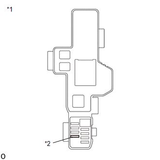
CHECK HARNESS AND CONNECTOR (INVERTER WATER PUMP ASSEMBLY CIRCUIT) |
(a) Remove the INV W/P relay and INV W/P NO. 2 fuse from the No. 1 engine room relay block and junction block assembly.
(b) Disconnect the A53 inverter water pump assembly connector.
(c) Measure the resistance according to the value(s) in the table below.
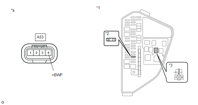
|
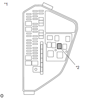
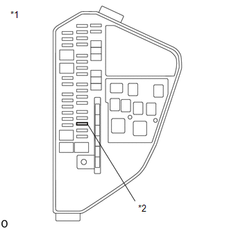
*1 |
No. 1 Engine Room Relay Block and Junction Block Assembly |
*2 |
INV W/P NO. 2 Fuse |
|
*3 |
INV W/P Relay |
- |
- |
|
*a |
Front view of wire harness connector (to Inverter Water Pump Assembly) |
- |
- |
Standard Resistance:
|
Tester Connection |
Condition |
Specified Condition |
|---|---|---|
|
A53-4 (+BWP) - 3 (INV W/P relay) |
Ignition switch off |
Below 1 Ω |
|
2 (INV W/P NO. 2 fuse) or A53-4 (+BWP) - Body ground and other terminals |
Ignition switch off |
10 kΩ or higher |
NOTICE:
Do not apply excessive force when using the probes of the tester to perform the inspection. If excessive force is used, the terminals will be damaged.
(d) Reconnect the A53 inverter water pump assembly connector.
(e) Install the INV W/P relay and INV W/P NO. 2 fuse.
| NG |
|
REPAIR OR REPLACE HARNESS OR CONNECTOR |
|
|
24. |
CHECK FUSE (INV W/P NO. 2) |
|
(a) Remove the INV W/P NO. 2 fuse from the No. 1 engine room relay block and junction block assembly. |
|
(b) Measure the resistance according to the value(s) in the table below.
Standard Resistance:
|
Tester Connection |
Condition |
Specified Condition |
|---|---|---|
|
INV W/P NO. 2 fuse |
Always |
Below 1 Ω |
(c) Install the INV W/P NO. 2 fuse.
| OK |
|
REPAIR OR REPLACE HARNESS OR CONNECTOR (INV W/P NO. 2 FUSE HOLDER TERMINAL OR INV W/P RELAY HOLDER TERMINAL) |
| NG |
|
|
25. |
INSPECT RELAY (INV W/P) |
|
(a) Remove the INV W/P relay from the No. 1 engine room relay block and junction block assembly. |
|
|
(b) Measure the resistance according to the value(s) in the table below. Standard Resistance:
|
|
(c) Install the INV W/P relay.
| OK |
|
CONNECT SECURELY (INV W/P NO. 1 FUSE) |
| NG |
|
|
26. |
CHECK FUSE HOLDER TERMINAL (INV W/P NO. 1 FUSE) |
|
(a) Check the terminals of the INV W/P NO. 1 fuse holder. OK: The terminals of the INV W/P NO. 1 fuse holder are not bent, loose or corroded. |
|
| OK |
|
REPLACE FUSE (INV W/P NO.1) |
| NG |
|
|
27. |
REPAIR OR REPLACE HARNESS OR CONNECTOR (INV W/P RELAY HOLDER TERMINAL) |
(a) Repair or replace the terminals of the INV W/P relay holder.
| NEXT |
|
REPLACE RELAY (INV W/P) |
|
28. |
REPLACE INVERTER WATER PUMP ASSEMBLY |
Click here
|
|
29. |
ADD HV COOLANT AND PERFORM AIR BLEEDING |
(a) After replacing the inverter water pump with motor assembly, add HV coolant and perform air bleeding.
Click here
| NEXT |
|
REPLACE FUSE (INV W/P NO. 2) |
|
30. |
REPLACE RELAY (INV W/P) |
(a) Replace INV W/P relay.
| NEXT |
|
CONNECT SECURELY (INV W/P NO. 1 FUSE) |
|
31. |
REPAIR OR REPLACE HARNESS OR CONNECTOR (INV W/P NO. 1 FUSE HOLDER TERMINAL) |
| NEXT |
|
REPLACE FUSE (INV W/P NO.1) |
|
32. |
CHECK RELAY HOLDER TERMINAL (INV W/P RELAY) |
|
(a) Check the terminals of the INV W/P relay holder. OK: The terminals of the INV W/P relay holder are not bent, loose or corroded. |
|
| NG |
|
|
|
33. |
CHECK FUSE (INV W/P NO. 1) |
|
(a) Remove the INV W/P NO. 1 fuse from the No. 3 relay block and junction block assembly. |
|
(b) Measure the resistance according to the value(s) in the table below.
Standard Resistance:
|
Tester Connection |
Condition |
Specified Condition |
|---|---|---|
|
INV W/P NO. 1 fuse |
Always |
Below 1 Ω |
(c) Install the INV W/P NO. 1 fuse.
| OK |
|
REPLACE RELAY (INV W/P) |
| NG |
|
|
34. |
CHECK FUSE (INV W/P NO. 1) |
|
(a) Remove the INV W/P NO. 1 fuse from the No. 3 relay block and junction block assembly. |
|
(b) Measure the resistance according to the value(s) in the table below.
Standard Resistance:
|
Tester Connection |
Condition |
Specified Condition |
|---|---|---|
|
INV W/P NO. 1 fuse |
Always |
Below 1 Ω |
(c) Install the INV W/P NO. 1 fuse.
| NG |
|
|
|
35. |
REPAIR OR REPLACE HARNESS OR CONNECTOR (INV W/P RELAY HOLDER TERMINAL) |
(a) Repair or replace the terminals of the INV W/P relay holder.
| NEXT |
|
REPLACE RELAY (INV W/P) |
|
36. |
REPLACE RELAY (INV W/P) |
(a) Replace INV W/P relay.
| NEXT |
|
REPLACE FUSE (INV W/P NO. 1) |
|
37. |
REPAIR OR REPLACE HARNESS OR CONNECTOR (INV W/P RELAY HOLDER TERMINAL) |
(a) Repair or replace the terminals of the INV W/P relay holder.
|
|
38. |
REPLACE RELAY (INV W/P) |
(a) Replace INV W/P relay.
| NEXT |
|
REPLACE FUSE (INV W/P NO. 1) |
|
|
|