| Last Modified: 01-30-2024 | 6.11:8.1.0 | Doc ID: RM100000001H3FJ |
| Model Year Start: 2019 | Model: RAV4 HV | Prod Date Range: [02/2019 - ] |
| Title: HYBRID / BATTERY CONTROL: MOTOR GENERATOR CONTROL SYSTEM (for AWD with NICKEL METAL HYDRIDE BATTERY): TERMINALS OF ECU; 2019 - 2024 MY RAV4 HV [02/2019 - ] | ||
TERMINALS OF ECU
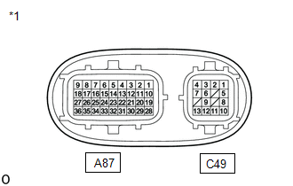
|
*1 |
Inverter with Converter Assembly |
HINT:
Since the inverter with converter assembly uses waterproof connectors, the voltage and waveforms cannot be inspected directly. Standard voltage readings and waveforms are indicated for reference only.
Inverter with Converter Assembly
|
Terminal No. (Symbol) |
Wiring Color |
Input/Output |
Terminal Description |
Condition |
Standard Condition |
|---|---|---|---|---|---|
|
A87-1 (RRFG) - A87-28 (RRF) |
G - BR |
Output |
Rear motor resolver signal |
Rear motor resolver running |
Pulse generation (Waveform 7) |
|
A87-3 (HMCH) - A87-9 (GND1) |
B - W-B |
Input/Output |
Communication signal |
Ignition switch ON |
Pulse generation (Waveform 4) |
|
A87-4 (HMCL) - A87-9 (GND1) |
W - W-B |
Input/Output |
Communication signal |
Ignition switch ON |
Pulse generation (Waveform 4) |
|
A87-6 (HSDN) - A87-9 (GND1) |
G - W-B |
Input |
MG shutdown signal |
Ignition switch ON (READY) |
0 to 1 V |
|
A87-10 (RSNG) - A87-19 (RSN) |
R - L |
Input |
Rear motor resolver signal |
Rear motor resolver running |
Pulse generation (Waveform 7) |
|
A87-16 (GI) - A87-9 (GND1) |
R - W-B |
Input |
Camshaft position sensor signal |
Ignition switch ON (READY), engine running |
Pulse generation (Waveform 2) |
|
A87-17 (NE) - A87-9 (GND1) |
B - W-B |
Input |
Crankshaft position sensor signal |
Ignition switch ON (READY), engine running |
Pulse generation (Waveform 3) |
|
A87-18 (ABFS) - A87-9 (GND1) |
LG - W-B |
Input |
Airbag activation signal |
Ignition switch ON (READY) |
Pulse generation (Waveform 9) |
|
A87-20 (RCSG) - A87-29 (RCS) |
Y - W |
Input |
Rear motor resolver signal |
Rear motor resolver running |
Pulse generation (Waveform 7) |
|
A87-22 (CANH) - A87-9 (GND1) |
V - W-B |
Input/Output |
CAN communication signal |
Ignition switch ON |
Pulse generation (Waveform 1) |
|
A87-24 (CNH2) - A87-9 (GND1) |
LG - W-B |
Input/Output |
CAN communication signal |
Ignition switch ON |
Pulse generation (Waveform 8) |
|
A87-26 (IGCT) - A87-9 (GND1) |
BE - W-B |
Input |
Motor generator control ECU (MG ECU) power source |
Ignition switch ON |
11 to 14 V |
|
A87-27 (+B3) - A87-9 (GND1) |
L - W-B |
Input |
Discharge control power source |
Always |
11 to 14 V |
|
A87-31 (CANL) - A87-9 (GND1) |
W - W-B |
Input/Output |
CAN communication signal |
Ignition switch ON |
Pulse generation (Waveform 1) |
|
A87-33 (CNL2) - A87-9 (GND1) |
W - W-B |
Input/Output |
CAN communication signal |
Ignition switch ON |
Pulse generation (Waveform 8) |
|
A87-35 (+B2) - A87-9 (GND1) |
GR - W-B |
Input |
Motor generator control ECU (MG ECU) power source |
Ignition switch ON |
11 to 14 V |
|
A87-36 (+B) - A87-9 (GND1) |
W - W-B |
Input |
Motor generator control ECU (MG ECU) power source |
Ignition switch ON |
11 to 14 V |
|
C49-1 (MSN) - C49-2 (MSNG) |
G - Y |
Input |
Motor resolver signal |
Motor resolver running |
Pulse generation (Waveform 5) |
|
C49-3 (MCSG) - C49-4 (MCS) |
B - L |
Input |
Motor resolver signal |
Motor resolver running |
Pulse generation (Waveform 5) |
|
C49-5 (MRF) - C49-6 (MRFG) |
W - R |
Output |
Motor resolver reference signal |
Motor resolver running |
Pulse generation (Waveform 5) |
|
C49-8 (GRF) - C49-9 (GRFG) |
SB - V |
Output |
Generator resolver reference signal |
Generator resolver running |
Pulse generation (Waveform 6) |
|
C49-10 (GSN) - C49-11 (GSNG) |
GR - P |
Input |
Generator resolver signal |
Generator resolver running |
Pulse generation (Waveform 6) |
|
C49-12 (GCSG) - C49-13 (GCS) |
BR - LG |
Input |
Generator resolver signal |
Generator resolver running |
Pulse generation (Waveform 6) |
NOTICE:
Do not measure the voltage or waveform on the sealed side of the inverter with converter assembly connector. Doing so may damage the connector because the connector is waterproof.
Oscilloscope waveforms
HINT:
Oscilloscope waveforms shown in the illustrations are examples for reference only. Noise, chattering, etc. are not shown.
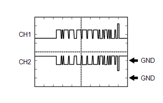
(a) Waveform 1 (CAN communication signal)
|
Item |
Content |
|---|---|
|
Terminal |
CH1: A87-22 (CANH) - A87-9 (GND1) CH2: A87-31 (CANL) - A87-9 (GND1) |
|
Equipment Setting |
1 V/DIV., 50 μs./DIV. |
|
Condition |
Ignition switch ON |
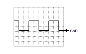
(b) Waveform 2 (camshaft position sensor signal)
|
Item |
Content |
|---|---|
|
Terminal |
A87-16 (GI) - A87-9 (GND1) |
|
Equipment Setting |
5 V/DIV., 20 ms./DIV. |
|
Condition |
Ignition switch ON (READY), engine running |
HINT:
The wavelength becomes shorter as the engine speed increases.
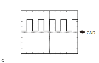
(c) Waveform 3 (crankshaft position sensor signal)
|
Item |
Content |
|---|---|
|
Terminal |
A87-17 (NE) - A87-9 (GND1) |
|
Equipment Setting |
5 V/DIV., 20 ms./DIV. |
|
Condition |
Ignition switch ON (READY), engine running |
HINT:
The wavelength becomes shorter as the engine speed increases.
(d) Waveform 4 (communication signal)
|
Item |
Content |
|---|---|
|
Terminal |
CH1: A87-3 (HMCH) - A87-9 (GND1) CH2: A87-4 (HMCL) - A87-9 (GND1) |
|
Equipment Setting |
1 V/DIV., 50 μs./DIV. |
|
Condition |
Ignition switch ON |
HINT:
The waveform will vary depending on the content of the digital communication (digital signal).
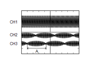
(e) Waveform 5 (motor resolver signal)
|
Item |
Content |
|---|---|
|
Terminal |
CH1: C49-5 (MRF) - C49-6 (MRFG) CH2: C49-1 (MSN) - C49-2 (MSNG) CH3: C49-4 (MCS) - C49-3 (MCSG) |
|
Equipment Setting |
CH1: 10 V/DIV., 1 ms./DIV. CH2: 5 V/DIV., 1 ms./DIV. CH3: 5 V/DIV., 1 ms./DIV. |
|
Condition |
Motor resolver running |
HINT:
The width indicated by (A) becomes shorter as the rotor speed increases.
(f) Waveform 6 (generator resolver signal)
|
Item |
Content |
|---|---|
|
Terminal |
CH1: C49-8 (GRF) - C49-9 (GRFG) CH2: C49-10 (GSN) - C49-11 (GSNG) CH3: C49-13 (GCS) - C49-12 (GCSG) |
|
Equipment Setting |
CH1: 10 V/DIV., 1 ms./DIV. CH2: 5 V/DIV., 1 ms./DIV. CH3: 5 V/DIV., 1 ms./DIV. |
|
Condition |
Generator resolver running |
HINT:
The width indicated by (A) becomes shorter as the rotor speed increases.
(g) Waveform 7 (rear motor resolver signal)
|
Item |
Content |
|---|---|
|
Terminal |
CH1: A87-28 (RRF) - A87-1 (RRFG) CH2: A87-19 (RSN) - A87-10 (RSNG) CH3: A87-29 (RCS) - A87-20 (RCSG) |
|
Equipment Setting |
CH1: 10 V/DIV., 1 ms./DIV. CH2: 5 V/DIV., 1 ms./DIV. CH3: 5 V/DIV., 1 ms./DIV. |
|
Condition |
Rear motor resolver running |
HINT:
The width indicated by (A) becomes shorter as the rotor speed increases.
(h) Waveform 8 (communication signal)
|
Item |
Content |
|---|---|
|
Terminal |
CH1: A87-24 (CNH2) - A87-9 (GND1) CH2: A87-33 (CNL2) - A87-9 (GND1) |
|
Equipment Setting |
1 V/DIV., 50 μs./DIV. |
|
Condition |
Ignition switch ON |
HINT:
The waveform will vary depending on the content of the digital communication (digital signal).
(i) Waveform 9 (Airbag activation signal)
|
Item |
Content |
|---|---|
|
Terminal |
A87-18 (ABFS) - A87-9 (GND1) |
|
Equipment Setting |
5 V/DIV., 150 ms./DIV. |
|
Condition |
Ignition switch ON (READY) |
|
|
|