| Last Modified: 05-08-2025 | 6.11:8.1.0 | Doc ID: RM100000001GILC |
| Model Year Start: 2019 | Model: RAV4 | Prod Date Range: [11/2018 - 10/2019] |
| Title: BRAKE SYSTEM (OTHER): BRAKE BOOSTER (w/ Vacuum Brake Booster): REMOVAL; 2019 MY RAV4 RAV4 HV [11/2018 - 10/2019] | ||
REMOVAL
CAUTION / NOTICE / HINT
The necessary procedures (adjustment, calibration, initialization or registration) that must be performed after parts are removed and installed, or replaced during brake booster assembly removal/installation are shown below.
Necessary Procedures After Parts Removed/Installed/Replaced
|
Replaced Part or Performed Procedures |
Necessary Procedures |
Effect/Inoperative Function When Necessary Procedures are not Performed |
Link |
|---|---|---|---|
|
*: When performing learning using the Techstream.
Click here
|
|||
|
Battery terminal is disconnected/reconnected |
Drive the vehicle until stop and start control is permitted (approximately 5 to 60 minutes) |
Stop and start system |
|
|
Perform steering sensor zero point calibration |
Lane control system |
|
|
|
Parking support brake system (for Gasoline model)* |
|||
|
Pre-collision system |
|||
|
Memorize steering angle neutral point |
Parking assist monitor system |
|
|
|
Panoramic view monitor system (for Gasoline model) |
|
||
|
Reset back door close position |
Power back door system (for Gasoline model) |
|
|
|
Back door lock initialization |
Power door lock control system |
|
|
NOTICE:
- After the ignition switch is turned off, the radio and display receiver assembly records various types of memory and settings. As a result, after turning the ignition switch off, be sure to wait for the time specified in the following table before disconnecting the cable from the negative (-) battery terminal.
- Make sure to release vacuum from the brake booster assembly before removing the brake master cylinder sub-assembly from the brake booster assembly.
Waiting Time before Disconnecting Cable from Negative (-) Battery Terminal
|
System Name |
See Procedure |
|---|---|
|
Vehicle enrolled in Toyota Entune system or safety connect system |
6 minutes |
|
Vehicle not enrolled in Toyota Entune system and safety connect system |
1 minute |
PROCEDURE
1. PRECAUTION
CAUTION:
Be sure to read precaution thoroughly before servicing.
-
w/ Occupant Classification System:
Click here
![2019 MY RAV4 RAV4 HV [11/2018 - 02/2019]; SUPPLEMENTAL RESTRAINT SYSTEMS: AIRBAG SYSTEM (w/ Occupant Classification System): PRECAUTION](/t3Portal/stylegraphics/info.gif)
-
w/o Occupant Classification System:
Click here
NOTICE:
After turning the ignition switch off, waiting time may be required before disconnecting the cable from the negative (-) auxiliary battery terminal. Therefore, make sure to read the disconnecting the cable from the negative (-) auxiliary battery terminal notices before proceeding with work.
Click here
2. REMOVE BRAKE MASTER CYLINDER SUB-ASSEMBLY
Click here
3. REMOVE ECM
Click here
4. REMOVE BATTERY CLAMP SUB-ASSEMBLY
Click here
5. REMOVE LOWER NO. 1 INSTRUMENT PANEL AIRBAG ASSEMBLY
Click here
6. REMOVE NO. 1 AIR DUCT (for TMC Made)
Click here
7. REMOVE NO. 2 AIR DUCT SUB-ASSEMBLY (for TMMC Made)
Click here
8. REMOVE STOP LIGHT SWITCH ASSEMBLY
Click here
9. REMOVE BRAKE PEDAL RETURN SPRING
Click here
10. SEPARATE WIRE HARNESS
|
(a) Disconnect the connector. |
|
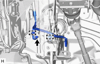
(b) Disengage the 2 clamps to separate the wire harness from the brake pedal support assembly.
11. LOOSEN LOCK NUT
|
(a) Loosen the lock nut of the brake master cylinder push rod clevis. |
|
12. REMOVE PUSH ROD PIN
Click here
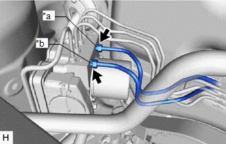
13. DISCONNECT CHECK VALVE TO CONNECTOR TUBE HOSE
|
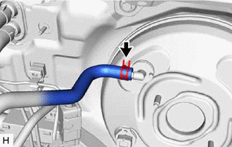
(a) Slide the clip and disconnect the check valve to connector tube hose from the brake booster assembly. |
|
14. REMOVE BRAKE BOOSTER ASSEMBLY
|
(a) Remove the bolt and nut. |
|
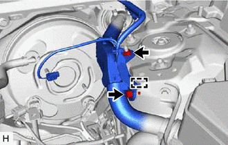
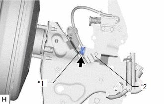
(b) Disengage the guide and separate the wire harness.
(c) Apply protective tape to the vehicle body as shown in the illustration.
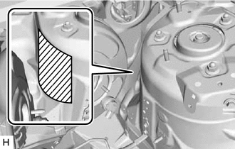

|
Protective Tape |
|
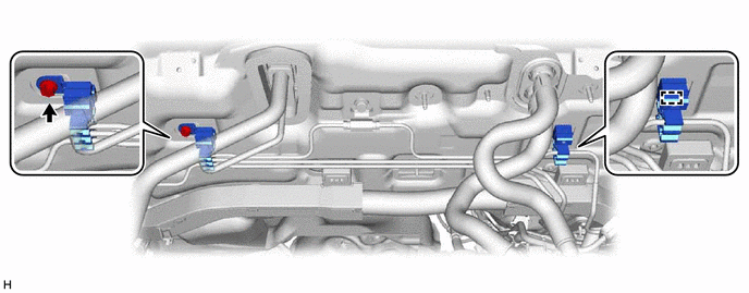
(d) Disconnect the connector from the vacuum warning switch assembly. |
|
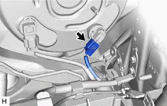
|
(e) w/ Stop and Start System: (1) Disconnect the connector from the vacuum sensor assembly. |
|
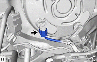
|
(f) Disengage the 5 clamps to separate the brake tube clamp from the brake lines. |
|
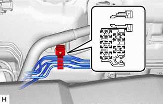
|
(g) Disengage the 5 clamps to remove the brake tube clamp from the brake lines. |
|
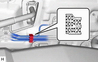
|
(h) Disengage the 5 clamps to remove the brake tube clamp from the brake lines. |
|
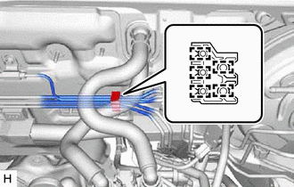
|
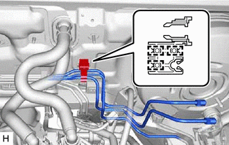
(i) Disengage the 3 clamps to separate the brake tube clamp from the brake lines. |
|
(j) Remove the bolt and clamp to remove the 2 brake tube clamps from the vehicle body.
|
(k) Using a union nut wrench, remove the 2 brake lines from the brake actuator assembly. NOTICE:
|
|
|
(l) Remove the 4 nuts. NOTICE: Do not apply excessive force to the brake lines. |
|
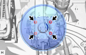
(m) Remove the brake master cylinder push rod clevis and lock nut from the brake booster assembly.
(n) Remove the brake booster assembly from the vehicle body.
NOTICE:
Do not apply excessive force to the brake lines.
15. REMOVE BRAKE BOOSTER GASKET
(a) Remove the brake booster gasket from the brake booster assembly.
|
|
|