|
Last Modified: 01-30-2024 |
6.11:8.1.0 |
Doc ID: RM100000001G22F |
|
Model Year Start: 2019 |
Model: RAV4 |
Prod Date Range: [11/2018 -
] |
|
Title: THEFT DETERRENT / KEYLESS ENTRY: SMART KEY SYSTEM (for Start Function, Gasoline Model): Power Source Mode does not Change to ON (IG); 2019 - 2024 MY RAV4 [11/2018 - ] |
|
Power Source Mode does not Change to ON (IG)
|
DESCRIPTION
If the engine switch is pressed with the electrical key transmitter sub-assembly in the cabin, the certification ECU (smart key ECU assembly) receives a signal and changes the power source mode.
Related Data List and Active Test Items
|
Problem Symptom
|
Data List and Active Test
|
|
Power source mode does not change to on (IG) but does change to on (ACC)
|
Power Source Control
-
Power Supply Condition
-
IG Relay Monitor (Inside)
-
IG Relay Monitor (Outside)
|
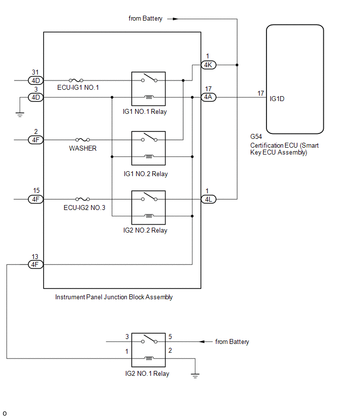
WIRING DIAGRAM
CAUTION / NOTICE / HINT
PROCEDURE
(a) Connect the Techstream to the DLC3.
(b) Turn the engine switch on (IG).
(c) Turn the Techstream on.
(d) Enter the following menus: Body Electrical / Smart Key, Power Source Control / Trouble Codes.
(e) Check for DTCs.
Body Electrical > Smart Key > Trouble Codes
Body Electrical > Power Source Control > Trouble Codes
|
Result
|
Proceed to
|
|
DTCs are not output
|
A
|
|
Smart key system (for Start Function) DTCs are output
|
B
|
|
A
|

|
|
|
2.
|
CHECK CERTIFICATION ECU (SMART KEY ECU ASSEMBLY)
|
|
(a) Measure the voltage according to the value(s) in the table below.
Standard Voltage:
|
Tester Connection
|
Switch Condition
|
Specified Condition
|
|
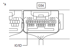
G54-17 (IG1D) - Body ground
|
Engine switch on (ACC) → Engine switch on (IG)
|
1 V or less → 9 V or higher
|
|
|
|
*a
|
Component with harness connected
(Certification ECU (Smart Key ECU Assembly))
|
|
|
|
OK
|
|
|
|
|
3.
|
CHECK HARNESS AND CONNECTOR (INSTRUMENT PANEL JUNCTION BLOCK ASSEMBLY - CERTIFICATION ECU (SMART KEY ECU ASSEMBLY), POWER SUPPLY AND BODY GROUND)
|
(a) Disconnect the G54 certification ECU (smart key ECU assembly) connector.
(b) Disconnect the 4A, 4D and 4L instrument panel junction block assembly connectors.
(c) Measure the resistance according to the value(s) in the table below.
Standard Resistance:
|
Tester Connection
|
Condition
|
Specified Condition
|
|
G54-17 (IG1D) - 4A-17
|
Always
|
Below 1 Ω
|
|
4D-3 - Body ground
|
Always
|
Below 1 Ω
|
|
G54-17 (IG1D) or 4A-17 - Other terminals and body ground
|
Always
|
10 kΩ or higher
|
(d) Measure the voltage according to the value(s) in the table below.
Standard Voltage:
|
Tester Connection
|
Condition
|
Specified Condition
|
|
4K-1 - Body ground
|
Always
|
11 to 14 V
|
|
4L-1 - Body ground
|
Always
|
11 to 14 V
|
(e) Reconnect the G54 certification ECU (smart key ECU assembly) connector.
| NG |

|
REPAIR OR REPLACE HARNESS OR CONNECTOR
|
|
OK
|
|
|
|
|
4.
|
CHECK INSTRUMENT PANEL JUNCTION BLOCK ASSEMBLY
|
|
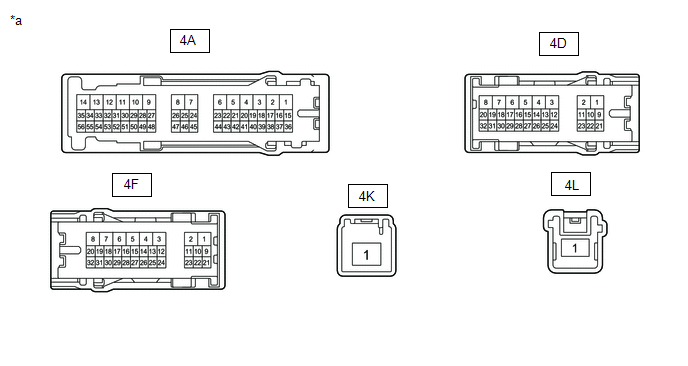
*a
|
Component without harness connected
(Instrument Panel Junction Block Assembly)
|
-
|
-
|
(a) Remove the instrument panel junction block assembly.
Click here
![2019 MY RAV4 RAV4 HV [11/2018 - 02/2019]; POWER DISTRIBUTION: MAIN BODY ECU: REMOVAL](/t3Portal/stylegraphics/info.gif)
(b) Reconnect the instrument panel junction block assembly connectors.
(c) Measure the resistance according to the value(s) in the table below.
Standard Resistance:
|
Tester Connection
|
Condition
|
Specified Condition
|
|
4A-17 - 4F-13
|
Always
|
Below 1 Ω
|
(d) Connect a positive (+) lead from the battery to terminal 4A-17.
(e) Connect a negative (-) lead from the battery to terminal 4D-3.
(f) Measure the resistance according to the value(s) in the table below.
Standard Resistance:
|
Tester Connection
|
Condition
|
Specified Condition
|
|
4K-1 - 4D-31
|
Always
|
Below 1 Ω
|
|
4K-1 - 4F-2
|
Always
|
Below 1 Ω
|
|
4L-1 - 4F-15
|
Always
|
Below 1 Ω
|
|
OK
|
|
|
|
|
5.
|
CHECK HARNESS AND CONNECTOR (IG2 NO. 1 RELAY - INSTRUMENT PANEL JUNCTION BLOCK ASSEMBLY, POWER SUPPLY AND BODY GROUND)
|
(a) Disconnect the 4F instrument panel junction block assembly connector.
(b) Remove the IG2 NO.1 relay.
(c) Measure the resistance according to the value(s) in the table below.
Standard Resistance:
|
Tester Connection
|
Condition
|
Specified Condition
|
|
4F-13 - IG2 NO.1 relay installation terminal 1
|
Always
|
Below 1 Ω
|
|
IG2 NO.1 relay installation terminal 2 - Body ground
|
Always
|
Below 1 Ω
|
|
4F-13 or IG2 NO.1 relay installation terminal 1 - Other terminals and body ground
|
Always
|
10 kΩ or higher
|
(d) Measure the voltage according to the value(s) in the table below.
Standard Voltage:
|
Tester Connection
|
Condition
|
Specified Condition
|
|
IG2 NO.1 relay installation terminal 5 - Body ground
|
Always
|
11 to 14 V
|
| NG |
|
REPAIR OR REPLACE HARNESS OR CONNECTOR
|
|
OK
|
|
|
|
|
6.
|
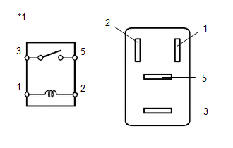
INSPECT IG2 NO. 1 RELAY
|
|
(a) Measure the resistance according to the value(s) in the table below.
Standard Resistance:
|
Tester Connection
|
Condition
|
Specified Condition
|
|
3 - 5
|
Battery voltage applied between terminals 1 and 2
|
Below 1 Ω
|
|
Battery voltage not applied between terminals 1 and 2
|
10 kΩ or higher
|
|
|
| NG |
|
REPLACE IG2 NO. 1 RELAY
|
|