|
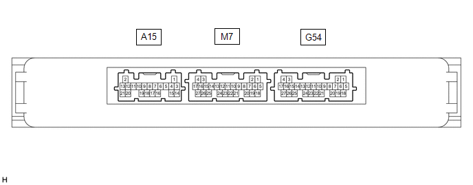
G54-17 (IG1D) - G54-18 (E)
|
L - W-B
|
Output
|
IG power supply
|
Engine switch off → on (IG)
|
1 V or less → 9 V or higher
|
Power Source Control
-
IG Relay Monitor (Outside)
|
|
G54-16 (ACCD) - G54-18 (E)
|
G - W-B
|
Output
|
ACC power supply
|
Engine switch off → on (ACC)
|
1 V or less → 8.5 V or higher
|
|
|
M7-17 (CLG1) - G54-18 (E)
|
R - W-B
|
Output
|
Output to driver door electrical key antenna
(request signal (challenge) is sent to door electrical key antenna from certification ECU (smart key ECU assembly) to form detection area)
|
Procedure:
-
Engine switch off
-
All doors closed
-
Electrical key transmitter sub-assembly not inside vehicle
-
All doors locked through wireless operation
(electrical key transmitter sub-assembly brought inside detection area*2)
|
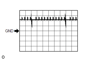
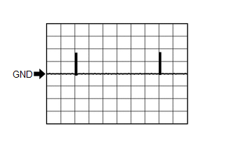
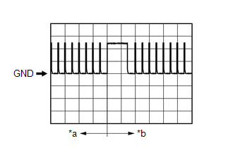
Pulse generation
(See waveform 1)
|
-
|
|
Procedure:
-
Engine switch off
-
All doors closed
-
Electrical key transmitter sub-assembly not inside vehicle
-
All doors locked through wireless operation
(electrical key transmitter sub-assembly brought outside detection area*2)
|
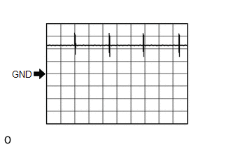
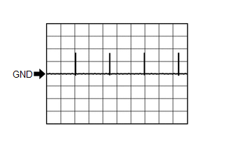
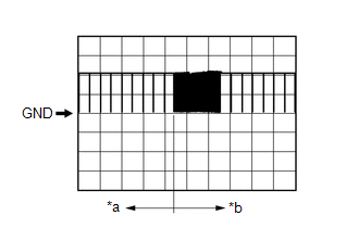
Pulse generation
(See waveform 2)
|
|
M7-17 (CLG1) - G54-18 (E)
|
R - W-B
|
Input
|
Input to driver door lock sensor
(front door outside handle assembly LH lock sensor ON signal is sent to the certification ECU (smart key ECU assembly))
|
Procedure:
-
Engine switch off
-
Electrical key transmitter sub-assembly brought outside vehicle
-
All doors closed
-
All doors locked through wireless operation
(electrical key transmitter sub-assembly brought outside detection area*2)
-
Driver door lock sensor touched
|
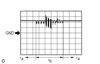
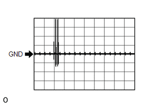
Pulse generation
(See waveform 3)
|
|
|
M7-17 (CLG1) - G54-18 (E)
|
R - W-B
|
Input
|
Input to driver door unlock sensor
(when system is in unlock standby mode and unlock sensor is touched, door electrical key antenna sends unlock sensor input signal (sensing) to certification ECU (smart key ECU assembly))
|
Procedure:
-
Engine switch off
-
Electrical key transmitter sub-assembly brought outside vehicle
-
All doors locked
-
Electrical key transmitter sub-assembly not near the vehicle
-
Driver door unlock sensor touched
|
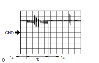
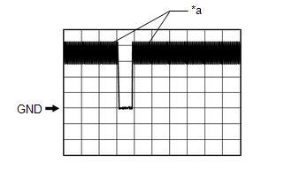
Pulse generation
(See waveform 4)
|
|
|
M7-16 (CG1B) - G54-18 (E)
|
GR - W-B
|
Output
|
Output to driver door electrical key antenna (terminal on opposite side of component from CLG1 output terminal)
|
Procedure:
-
Engine switch off
-
All doors closed
-
Electrical key transmitter sub-assembly not inside vehicle
-
All doors locked through wireless operation
(electrical key transmitter sub-assembly brought inside detection area*2)
|
Pulse generation
(See waveform 5)
|
-
|
|
Procedure:
-
Engine switch off
-
All doors closed
-
Electrical key transmitter sub-assembly not inside vehicle
-
All doors locked through wireless operation
(electrical key transmitter sub-assembly brought outside detection area*2)
|
Pulse generation
(See waveform 6)
|
|
M7-15 (CLG2) - G54-18 (E)
|
R - W-B
|
Output
|
Output to front passenger door electrical key antenna
(request signal (challenge) is sent to door electrical key antenna from certification ECU (smart key ECU assembly) to form detection area)
|
Procedure:
-
Engine switch off
-
All doors closed
-
Electrical key transmitter sub-assembly not inside vehicle
-
All doors locked through wireless operation
(electrical key transmitter sub-assembly brought inside detection area*2)
|
Pulse generation
(See waveform 1)
|
-
|
|
Procedure:
-
Engine switch off
-
All doors closed
-
Electrical key transmitter sub-assembly not inside vehicle
-
All doors locked through wireless operation
(electrical key transmitter sub-assembly brought outside detection area*2)
|
Pulse generation
(See waveform 2)
|
|
M7-15 (CLG2) - G54-18 (E)
|
R - W-B
|
Input
|
Input to front passenger door lock sensor
(front door outside handle assembly RH lock sensor ON signal is sent to the certification ECU (smart key ECU assembly))
|
Procedure:
-
Engine switch off
-
Electrical key transmitter sub-assembly brought outside vehicle
-
All doors closed
-
All doors locked through wireless operation
(electrical key transmitter sub-assembly brought outside detection area*2)
-
Front passenger door lock sensor touched
|
Pulse generation
(See waveform 3)
|
|
|
M7-15 (CLG2) - G54-18 (E)
|
R - W-B
|
Input
|
Input to front passenger door unlock sensor
(when system is in unlock standby mode and unlock sensor is touched, door electrical key antenna sends unlock sensor input signal (sensing) to certification ECU (smart key ECU assembly))
|
Procedure:
-
Engine switch off
-
Electrical key transmitter sub-assembly brought outside vehicle
-
All doors locked
-
Electrical key transmitter sub-assembly not near the vehicle
-
Front passenger door unlock sensor touched
|
Pulse generation
(See waveform 4)
|
|
|
M7-14 (CG2B) - G54-18 (E)
|
W - W-B
|
Output
|
Output to front passenger door electrical key antenna (terminal on opposite side of component from CLG2 output terminal)
|
Procedure:
-
Engine switch off
-
All doors closed
-
Electrical key transmitter sub-assembly not inside vehicle
-
All doors locked through wireless operation
(electrical key transmitter sub-assembly brought inside detection area*2)
|
Pulse generation
(See waveform 5)
|
-
|
|
Procedure:
-
Engine switch off
-
All doors closed
-
Electrical key transmitter sub-assembly not inside vehicle
-
All doors locked through wireless operation
(electrical key transmitter sub-assembly brought outside detection area*2)
|
Pulse generation
(See waveform 6)
|
|
M7-1 (CLG3) - G54-18 (E)*1
|
Output
|
BE - W-B
|
Output to rear door electrical key antenna LH
(request signal (challenge) is sent to door electrical key antenna from certification ECU (smart key ECU assembly) to form detection area)
|
Procedure:
-
Engine switch off
-
All doors closed
-
Electrical key transmitter sub-assembly not inside vehicle
-
All doors locked through wireless operation
(electrical key transmitter sub-assembly brought inside detection area*2)
|
Pulse generation
(See waveform 1)
|
-
|
|
Procedure:
-
Engine switch off
-
All doors closed
-
Electrical key transmitter sub-assembly not inside vehicle
-
All doors locked through wireless operation
(electrical key transmitter sub-assembly brought outside detection area*2)
|
Pulse generation
(See waveform 2)
|
|
M7-1 (CLG3) - G54-18 (E)*1
|
Input
|
BE - W-B
|
Input to rear door lock sensor LH
(rear door outside handle assembly LH lock sensor ON signal is sent to the certification ECU (smart key ECU assembly))
|
Procedure:
-
Engine switch off
-
Electrical key transmitter sub-assembly brought outside vehicle
-
All doors closed
-
All doors locked through wireless operation
(electrical key transmitter sub-assembly brought outside detection area*2)
-
Rear door LH lock sensor touched
|
Pulse generation
(See waveform 3)
|
|
|
M7-1 (CLG3) - G54-18 (E)*1
|
Input
|
BE - W-B
|
Input to rear door unlock sensor LH
(when system is in unlock standby mode and unlock sensor is touched, door electrical key antenna sends unlock sensor input signal (sensing) to certification ECU (smart key ECU assembly))
|
Procedure:
-
Engine switch off
-
Electrical key transmitter sub-assembly brought outside vehicle
-
All doors locked
-
Electrical key transmitter sub-assembly not near the vehicle
-
Rear door LH unlock sensor touched
|
Pulse generation
(See waveform 4)
|
|
|
M7-2 (CG3B) - G54-18 (E)*1
|
Output
|
GR - W-B
|
Output to rear door LH electrical key antenna (terminal on opposite side of component from CLG3 output terminal)
|
Procedure:
-
Engine switch off
-
All doors closed
-
Electrical key transmitter sub-assembly not inside vehicle
-
All doors locked through wireless operation
(electrical key transmitter sub-assembly brought inside detection area*2)
|
Pulse generation
(See waveform 5)
|
-
|
|
Procedure:
-
Engine switch off
-
All doors closed
-
Electrical key transmitter sub-assembly not inside vehicle
-
All doors locked through wireless operation
(electrical key transmitter sub-assembly brought outside detection area*2)
|
Pulse generation
(See waveform 6)
|
|
M7-9 (CLG4) - G54-18 (E)*1
|
Output
|
L - W-B
|
Output to rear door electrical key antenna RH
(request signal (challenge) is sent to door electrical key antenna from certification ECU (smart key ECU assembly) to form detection area)
|
Procedure:
-
Engine switch off
-
All doors closed
-
Electrical key transmitter sub-assembly not inside vehicle
-
All doors locked through wireless operation
(electrical key transmitter sub-assembly brought inside detection area*2)
|
Pulse generation
(See waveform 1)
|
-
|
|
Procedure:
-
Engine switch off
-
All doors closed
-
Electrical key transmitter sub-assembly not inside vehicle
-
All doors locked through wireless operation
(electrical key transmitter sub-assembly brought outside detection area*2)
|
Pulse generation
(See waveform 2)
|
|
M7-9 (CLG4) - G54-18 (E)*1
|
Input
|
L - W-B
|
Input to rear door lock sensor RH
(rear door outside handle assembly RH lock sensor ON signal is sent to the certification ECU (smart key ECU assembly))
|
Procedure:
-
Engine switch off
-
Electrical key transmitter sub-assembly brought outside vehicle
-
All doors closed
-
All doors locked through wireless operation
(electrical key transmitter sub-assembly brought outside detection area*2)
-
Rear door RH lock sensor touched
|
Pulse generation
(See waveform 3)
|
|
|
M7-9 (CLG4) - G54-18 (E)*1
|
Input
|
L - W-B
|
Input to rear door unlock sensor RH
(when system is in unlock standby mode and unlock sensor is touched, door electrical key antenna sends unlock sensor input signal (sensing) to certification ECU (smart key ECU assembly))
|
Procedure:
-
Engine switch off
-
Electrical key transmitter sub-assembly brought outside vehicle
-
All doors locked
-
Electrical key transmitter sub-assembly not near the vehicle
-
Rear door RH unlock sensor touched
|
Pulse generation
(See waveform 4)
|
|
|
M7-8 (CG4B) - G54-18 (E)*1
|
Output
|
GR - W-B
|
Output to rear door RH electrical key antenna (terminal on opposite side of component from CLG4 output terminal)
|
Procedure:
-
Engine switch off
-
All doors closed
-
Electrical key transmitter sub-assembly not inside vehicle
-
All doors locked through wireless operation
(electrical key transmitter sub-assembly brought inside detection area*2)
|
Pulse generation
(See waveform 5)
|
-
|
|
Procedure:
-
Engine switch off
-
All doors closed
-
Electrical key transmitter sub-assembly not inside vehicle
-
All doors locked through wireless operation
(electrical key transmitter sub-assembly brought outside detection area*2)
|
Pulse generation
(See waveform 6)
|
|
M7-13 (CLG8) - G54-18 (E)
|
R - W-B
|
Output
|
Output to electrical key antenna (outside luggage compartment)
|
Procedure:
-
Engine switch off
-
Electrical key transmitter sub-assembly brought outside vehicle
-
All doors closed
-
Back door opener switch assembly off → on
|
Pulse generation
(See waveform 7)
|
-
|
|
M7-12 (CG8B) - G54-18 (E)
|
L - W-B
|
Output
|
Output to electrical key antenna (outside luggage compartment) (terminal on opposite side of component from CLG8 output terminal)
|
Procedure:
-
Engine switch off
-
Electrical key transmitter sub-assembly brought outside vehicle
-
All doors closed
-
Back door opener switch assembly off → on
|
Pulse generation
(See waveform 7)
|
-
|
|
M7-26 (TSW5) - G54-18 (E)
|
B - W-B
|
Input
|
Back door opener switch assembly (unlock switch) signal input
|
Back door opener switch assembly (unlock switch) off → on
|
Pulse generation
(See waveform 8)
|
|
|
M7-27 (TSW6) - G54-18 (E)
|
R - W-B
|
Input
|
Back door opener switch assembly (lock switch) signal input
|
Back door opener switch assembly (lock switch) off → on
|
Pulse generation
(See waveform 8)
|
|
|
M7-18 (RCO) - G54-18 (E)
|
L - W-B
|
Output
|
Output to door control receiver
(Power supply for door control receiver. Certification ECU (smart key ECU assembly) outputs 5 V when receiver starts operating.)
|
Procedure:
-
Engine switch off
-
Electrical key transmitter sub-assembly brought outside detection area but kept inside wireless function operational area
-
Lock or unlock switch of electrical key transmitter sub-assembly not pressed → pressed
|
Pulse generation
(See waveform 9)
|
-
|
|
M7-19 (RDAM) - G54-18 (E)
|
G - W-B
|
Input
|
Door control receiver verifies data received from electrical key transmitter sub-assembly.
Door control receiver sends data from electrical key transmitter sub-assembly to certification ECU (smart key ECU assembly) (Door control receiver intermittently grounds 12 V signal from certification ECU (smart key ECU assembly)).
|
Proceed:
-
Engine switch off
-
All doors locked
-
Electrical key transmitter sub-assembly not inside vehicle
-
Electrical key transmitter sub-assembly brought outside detection area but kept inside wireless function operational area
-
Lock or unlock switch of electrical key transmitter sub-assembly not pressed → pressed
|
Pulse generation
(See waveform 10)
|
-
|
|
M7-20 (CSEL) - G54-18 (E)
|
BE - W-B
|
Output
|
Communication channel switching circuit
|
Procedure:
-
Engine switch off
-
All doors closed
|
Pulse generation
|
-
|
![2019 - 2023 MY RAV4 [11/2018 - 10/2023]; THEFT DETERRENT / KEYLESS ENTRY: SMART KEY SYSTEM (for Entry Function, Gasoline Model): OPERATION CHECK](/t3Portal/stylegraphics/info.gif)