| Last Modified: 01-30-2024 | 6.11:8.1.0 | Doc ID: RM100000001FWRH |
| Model Year Start: 2019 | Model: RAV4 | Prod Date Range: [11/2018 - ] |
| Title: LIGHTING (INT): LIGHTING SYSTEM: TERMINALS OF ECU; 2019 - 2024 MY RAV4 RAV4 HV [11/2018 - ] | ||
TERMINALS OF ECU
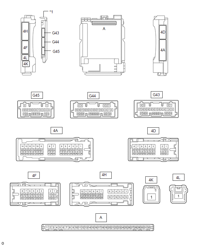
CHECK INSTRUMENT PANEL JUNCTION BLOCK ASSEMBLY AND MAIN BODY ECU (MULTIPLEX NETWORK BODY ECU)
|
*1 |
Main Body ECU (Multiplex Network Body ECU) |
- |
- |
(a) Remove the main body ECU (multiplex network body ECU) from the instrument panel junction block assembly.
Click here
![2019 MY RAV4 RAV4 HV [11/2018 - 02/2019]; POWER DISTRIBUTION: MAIN BODY ECU: REMOVAL](/t3Portal/stylegraphics/info.gif)
(b) Connect the instrument panel junction block assembly connectors.
(c) Measure the voltage and resistance according to the value(s) in the table below.
|
Terminal No. (Symbol) |
Wiring Color |
Terminal Description |
Condition |
Specified Condition |
|---|---|---|---|---|
|
A-32 (IG) - Body ground |
None - Body ground |
Ignition power supply |
Ignition switch ON |
11 to 14 V |
|
Ignition switch off |
Below 1 V |
|||
|
A-31 (BECU) - Body ground |
None - Body ground |
Auxiliary battery power supply |
Ignition switch off |
11 to 14 V |
|
A-30 (ACC) - Body ground |
None - Body ground |
ACC power supply |
Ignition switch ACC |
11 to 14 V |
|
Ignition switch off |
Below 1 V |
|||
|
A-11 (GND1) - Body ground |
None - Body ground |
Ground |
Always |
Below 1 Ω |
(d) Install the main body ECU (multiplex network body ECU).
Click here
(e) Measure the voltage and pulse according to the value(s) in the table below.
|
Terminal No. (Symbol) |
Wiring Color |
Terminal Description |
Condition |
Specified Condition |
|---|---|---|---|---|
|
*1: w/ Memory Call Function
*2: w/o Memory Call Function *3: w/ Footwell Light |
||||
|
G44-1 (FLCY) - Body ground |
R - Body ground |
Front door courtesy light switch assembly LH input |
Front door LH open |
Below 1 V |
|
Front door LH closed |
4.7 to 5.3 V |
|||
|
G44-6 (FRCY) - Body ground |
BE - Body ground |
Front door courtesy light switch assembly RH input |
Front door RH open |
Below 1 V |
|
Front door RH closed |
4.7 to 5.3 V |
|||
|
4H-24 - Body ground |
G - Body ground |
Rear door courtesy light switch assembly LH input |
Rear door LH open |
Below 1 V |
|
Rear door LH closed |
4.7 to 5.3 V |
|||
|
4A-31 - Body ground |
LA-V - Body ground |
Rear door courtesy light switch assembly RH input |
Rear door RH open |
Below 1 V |
|
Rear door RH closed |
4.7 to 5.3 V |
|||
|
4H-34 - Body ground |
B - Body ground |
Back door courtesy light switch input |
Back door open |
Below 1 V |
|
Back door closed |
4.7 to 5.3 V |
|||
|
4D-13 - Body ground |
W - Body ground |
Front door LH unlock detection switch input |
Front door LH locked |
Pulse generation |
|
Front door LH unlocked |
Below 1 V |
|||
|
4D-12 - Body ground |
W - Body ground |
Front door RH unlock detection switch input |
Front door RH locked |
Pulse generation |
|
Front door RH unlocked |
Below 1 V |
|||
|
4D-14 - Body ground*1 |
GR - Body ground |
Rear door LH unlock detection switch input |
Rear door LH locked |
Pulse generation |
|
Rear door LH unlocked |
Below 1 V |
|||
|
4D-14 - Body ground*2 |
GR - Body ground |
Rear door LH and rear door RH unlock detection switch input |
Rear door LH or rear door RH locked |
Pulse generation |
|
Rear door LH and rear door RH unlocked |
Below 1 V |
|||
|
G43-20 (LSWR) - Body ground*1 |
L - Body ground |
Rear door RH unlock detection switch input |
Rear door RH locked |
Pulse generation |
|
Rear door RH unlocked |
Below 1 V |
|||
|
G44-20 (BCYL) - Body ground |
GR - Body ground |
No. 1 luggage compartment light assembly output |
No. 1 luggage compartment light assembly off |
11 to 14 V |
|
No. 1 luggage compartment light assembly on |
Below 1 V |
|||
|
4A-36 - Body ground*3 |
LA-B - Body ground |
No. 1 interior illumination light assembly (footwell light) output |
No. 1 interior illumination light assembly (footwell light) off |
11 to 14 V |
|
No. 1 interior illumination light assembly (footwell light) on |
Below 1 V |
|||
|
4A-37 - Body ground*3 |
B - Body ground |
No. 2 interior illumination light assembly (footwell light) output |
No. 2 interior illumination light assembly (footwell light) off |
11 to 14 V |
|
No. 2 interior illumination light assembly (footwell light) on |
Below 1 V |
|||
|
4D-10 - Body ground |
B - Body ground |
Map light assembly, visor light assembly power supply |
DOME CUT relay off |
11 to 14 V |
|
DOME CUT relay on |
Below 1 V |
|||
|
4H-19 - Body ground |
LG - Body ground |
No. 1 luggage compartment light assembly input |
DOME CUT relay off |
11 to 14 V |
|
DOME CUT relay on |
Below 1 V |
|||
|
4A-53 - Body ground |
L - Body ground |
Taillight signal |
Ignition switch ON, light control switch TAIL |
11 to 14 V |
|
Ignition switch ON, light control switch off |
Below 1 V |
|||
|
4H-22 - Body ground |
LA-W - Body ground |
Taillight signal |
Ignition switch ON, light control switch TAIL |
11 to 14 V |
|
Ignition switch ON, light control switch off |
Below 1 V |
|||
|
4D-29 - Body ground |
LA-L - Body ground |
Interior lights drive output |
Interior lights off (when operated by illuminated entry system) |
11 to 14 V |
|
Interior lights on (when operated by illuminated entry system) |
Below 1 V |
|||
CHECK CERTIFICATION ECU (SMART KEY ECU ASSEMBLY) (w/ Smart Key System for HV Model)
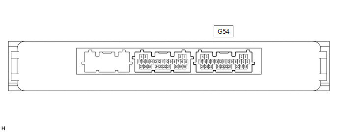
(a) Disconnect the G54 certification ECU (smart key ECU assembly) connector.
(b) Measure the voltage and resistance according to the value(s) in the table below.
|
Terminal No. (Symbol) |
Wiring Color |
Terminal Description |
Condition |
Specified Condition |
|---|---|---|---|---|
|
G54-4 (+B) - Body ground |
P - Body ground |
Auxiliary battery power supply |
Ignition switch off |
11 to 14 V |
|
G54-15 (CUTB) - Body ground |
V - Body ground |
Auxiliary battery power supply |
Ignition switch off |
11 to 14 V |
|
G54-18 (E) - Body ground |
W-B - Body ground |
Ground |
Always |
Below 1 Ω |
(c) Reconnect the G54 certification ECU (smart key ECU assembly) connector.
(d) Measure the voltage according to the value(s) in the table below.
|
Terminal No. (Symbol) |
Wiring Color |
Terminal Description |
Condition |
Specified Condition |
|---|---|---|---|---|
|
G54-10 (SWIL) - G54-11 (AGND) |
W - BE |
Push start switch illumination drive output |
Push start switch illumination on |
11 to 14 V |
|
Push start switch illumination off |
Below 1 V |
CHECK CERTIFICATION ECU (SMART KEY ECU ASSEMBLY) (w/ Smart Key System for Gasoline Model)
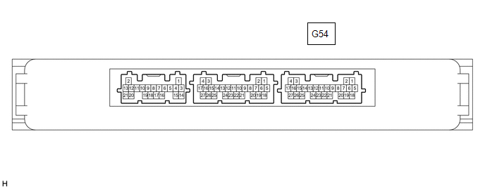
(a) Disconnect the G54 certification ECU (smart key ECU assembly) connector.
(b) Measure the voltage and resistance according to the value(s) in the table below.
|
Terminal No. (Symbol) |
Wiring Color |
Terminal Description |
Condition |
Specified Condition |
|---|---|---|---|---|
|
G54-4 (+B) - Body ground |
P - Body ground |
Auxiliary battery power supply |
Ignition switch off |
11 to 14 V |
|
G54-15 (CUTB)- Body ground |
V - Body ground |
Auxiliary battery power supply |
Ignition switch off |
11 to 14 V |
|
G54-18 (E) - Body ground |
W-B - Body ground |
Ground |
Always |
Below 1 Ω |
(c) Reconnect the G54 certification ECU (smart key ECU assembly) connector.
(d) Measure the voltage according to the value(s) in the table below.
|
Terminal No. (Symbol) |
Wiring Color |
Terminal Description |
Condition |
Specified Condition |
|---|---|---|---|---|
|
G54-10 (SWIL) - G54-11 (AGND) |
W - BE |
Push start switch illumination drive output |
Push start switch illumination on |
11 to 14 V |
|
Push start switch illumination off |
Below 1 V |
|
|
|