- N24-10 (LCV+) - N24-35 (LGND)
- N24-29 (CV+) - N24-32 (CGND)
- N24-36 (BCV+) - N24-37 (BGND)
- N24-38 (RCV+) - N24-17 (RGND)
| Last Modified: 01-30-2024 | 6.11:8.1.0 | Doc ID: RM100000001FPI7 |
| Model Year Start: 2019 | Model: RAV4 HV | Prod Date Range: [11/2018 - 10/2022] |
| Title: PARK ASSIST / MONITORING: PANORAMIC VIEW MONITOR SYSTEM (for HV Model): TERMINALS OF ECU; 2019 - 2022 MY RAV4 HV [11/2018 - 10/2022] | ||
TERMINALS OF ECU
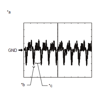
PARKING ASSIST ECU
(a) Disconnect the N25 parking assist ECU connector.
(b) Measure the voltage and resistance according to the value(s) in the table below.
|
Terminal No. (Symbol) |
Wiring Color |
Terminal Description |
Condition |
Specified Condition |
|---|---|---|---|---|
|
N25-1 (+B) - N25-4 (GND1) |
L - LA |
Power source signal |
Power switch off |
11 to 14 V |
|
N25-4 (GND1) - Body ground |
LA - Body ground |
Ground |
Always |
Below 1 Ω |
|
N25-3 (IG) - N25-4 (GND1) |
BE - LA |
IG power source signal |
Power switch on (IG) |
11 to 14 V |
|
Power switch off |
Below 1 V |
|||
|
N25-2 (ACC) - N25-4 (GND1) |
GR - LA |
ACC power source signal |
Power switch on (ACC) |
11 to 14 V |
|
Power switch off |
Below 1 V |
(c) Reconnect the N25 parking assist ECU connector.
(d) Measure the voltage, resistance and waveform according to the value(s) in the table below.
|
Terminal No. (Symbol) |
Wiring Color |
Terminal Description |
Condition |
Specified Condition |
|---|---|---|---|---|
|
N24-6 (RSW+) - N25-4 (GND1) |
BE - LA |
Terminal required by law |
Panoramic image being displayed |
0 to 2 V |
|
Panoramic image not being displayed |
5.5 to 7.05 V |
|||
|
N24-7 (NS+) - N24-24 (NS-) |
B - W |
Video signal |
Power switch on (IG), panoramic view monitor switch on, camera lens not covered, displaying image |
Pulse generation (See waveform 3) |
|
N24-8 (NSG) - Body ground |
BR - Body ground |
Shield ground |
Always |
Below 1 Ω |
|
N24-10 (LCV+) - N24-35 (LGND) |
W - G |
Side television camera assembly LH display signal input |
Power switch on (IG), panoramic view monitor switch on, camera lens not covered, displaying image |
Pulse generation (See waveform 1) |
|
Power switch on (IG), panoramic view monitor switch on, camera lens covered, blacking out screen |
Pulse generation (See waveform 2) |
|||
|
N24-11 (SGND) - Body ground |
BR - Body ground |
Side television camera assembly LH ground (shield) |
Always |
Below 1 Ω |
|
N24-12 (LCB+) - N24-35 (LGND) |
B - G |
Power source to side television camera assembly LH |
Power switch on (IG) |
5.5 to 7.05 V |
|
N24-13 (BCV-) - N24-37 (BGND) |
W - R |
Front television camera assembly display ground |
Always |
Below 1 Ω |
|
N24-14 (SGND) - Body ground |
BR - Body ground |
Front television camera assembly ground (shield) |
Always |
Below 1 Ω |
|
N24-15 (BCB+) - N24-37 (BGND) |
G - R |
Power source to front television camera |
Power switch on (IG) |
5.5 to 7.05 V |
|
N24-16 (RCV-) - N24-17 (RGND) |
R - G |
Side television camera assembly RH display ground |
Always |
Below 1 Ω |
|
N24-17 (RGND) - Body ground |
G - Body ground |
Side television camera assembly RH display ground |
Always |
Below 1 Ω |
|
N24-24 (NS-) - N25-4 (GND1) |
W - LA |
Video ground |
Always |
Below 1 Ω |
|
N24-29 (CV+) - N24-32 (CGND) |
B - G |
Television camera assembly display signal input |
Power switch on (IG), panoramic view monitor switch on, camera lens not covered, displaying image |
Pulse generation (See waveform 1) |
|
Power switch on (IG), panoramic view monitor switch on, camera lens covered, blacking out screen |
Pulse generation (See waveform 2) |
|||
|
N24-30 (CV-) - N24-32 (CGND) |
W - G |
Television camera assembly display ground |
Always |
Below 1 Ω |
|
N24-31 (SGND) - Body ground |
B - Body ground |
Television camera assembly ground (shield) |
Always |
Below 1 Ω |
|
N24-32 (CGND) - Body ground |
G - Body ground |
Television camera assembly ground |
Always |
Below 1 Ω |
|
N24-33 (CB+) - N24-32 (CGND) |
R - G |
Power source to television camera assembly |
Power switch on (IG) |
5.5 to 7.05 V |
|
N24-34 (LCV-) - N24-35 (LGND) |
R - G |
Side television camera assembly LH display ground |
Always |
Below 1 Ω |
|
N24-35 (LGND) - Body ground |
G - Body ground |
Side television camera assembly LH ground |
Always |
Below 1 Ω |
|
N24-36 (BCV+) - N24-37 (BGND) |
B - R |
Front television camera assembly display signal input |
Waveform 1: Power switch on (IG), panoramic view monitor switch on, camera lens not covered, displaying image |
Pulse generation (See waveform 1) |
|
Waveform 2: Power switch on (IG), panoramic view monitor switch on, camera lens covered, blacking out screen |
Pulse generation (See waveform 2) |
|||
|
N24-37 (BGND) - Body ground |
R - Body ground |
Front television camera assembly display ground |
Always |
Below 1 Ω |
|
N24-38 (RCV+) - N24-17 (RGND) |
W - G |
Side television camera assembly RH display signal input |
Waveform 1: Power switch on (IG), panoramic view monitor switch on, camera lens not covered, displaying image |
Pulse generation (See waveform 1) |
|
Waveform 2: Power switch on (IG), panoramic view monitor switch on, camera lens covered, blacking out screen |
Pulse generation (See waveform 2) |
|||
|
N24-39 (SGND) - Body ground |
BR - Body ground |
Side television camera assembly RH ground (shield) |
Always |
Below 1 Ω |
|
N24-40 (RCB+) - N24-17 (RGND) |
B - G |
Power source to side television camera assembly RH |
Power switch on (IG) |
5.5 to 7.05 V |
|
N25-11 (CANH) |
GR |
CAN communication line |
- |
- |
|
N25-12 (CANL) |
W |
CAN communication line |
- |
- |
|
N25-14 (REV) - N25-4 (GND1) |
W - LA |
Reverse signal input |
Power switch on (IG), panoramic view monitor switch on, shift lever in R |
Below 1 V |
|
Power switch on (IG), panoramic view monitor switch on, shift lever except R |
11 to 14 V |
|||
|
N25-15 (BLSW) - N25-4 (GND1) |
G - LA |
Panoramic view monitor switch signal |
Power switch on (IG), panoramic view monitor switch off |
5.5 to 6.5 V |
|
Power switch on (IG), panoramic view monitor switch on |
Below 1 V |
|||
|
N25-16 (MPOS) - N25-4 (GND1)* |
L - LA |
Outer rear view mirror status signal input |
Power switch on (IG), retractable outer mirror switch on |
Below 1 V |
|
Power switch on (IG), retractable mirror switch off |
11 to 14 V |
- *: w/ Retract Mirror
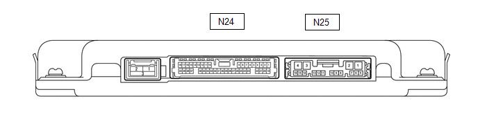
(e) Using an oscilloscope, check the waveform.
|
*a |
Waveform 1 |
*b |
Waveform 2 |
|
*c |
Synchronization Signal |
*d |
Video Waveform |
(1) Waveform 1, 2
Measurement Condition
|
Item |
Content |
|---|---|
|
Terminal No. (Symbol) |
|
|
Tool Setting |
200 mV/DIV., 50 μsec./DIV. |
|
Condition |
|
HINT:
- The video waveform changes according to the image sent by the television camera assembly.
- The video waveform is constantly output when the power switch is on (ACC).
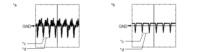
(2) Waveform 3
|
Item |
Content |
|---|---|
|
Measurement terminal |
N24-7 (NS+) - N24-24 (NS-) |
|
Measurement setting |
200 mV/DIV., 50 μs./DIV. |
|
Condition |
Power switch on (IG), panoramic view monitor switch on, camera lens not covered, displaying image |
|
*a |
Waveform 3 (camera lens is not covered, displaying an image) |
|
*b |
Synchronization Signal |
|
*c |
Video Waveform |
HINT:
The video waveform changes according to the image sent by the parking assist ECU.
RADIO AND DISPLAY RECEIVER ASSEMBLY (w/ Audio and Visual System)
Click here
![2019 MY RAV4 RAV4 HV [11/2018 - 10/2019]; AUDIO / VIDEO: AUDIO AND VISUAL SYSTEM: TERMINALS OF ECU](/t3Portal/stylegraphics/info.gif)
RADIO AND DISPLAY RECEIVER ASSEMBLY (w/ Navigation System)
Click here
|
|
|