- Blower airflow volume is weak
- Blower airflow volume cannot be changed
| Last Modified: 09-02-2025 | 6.11:8.1.0 | Doc ID: RM100000001FPEK |
| Model Year Start: 2019 | Model: RAV4 | Prod Date Range: [11/2018 - ] |
| Title: HEATING / AIR CONDITIONING: AIR CONDITIONING SYSTEM (for Gasoline Model): Blower Motor Circuit; 2019 - 2025 MY RAV4 [11/2018 - ] | ||
|
Blower Motor Circuit |
DESCRIPTION
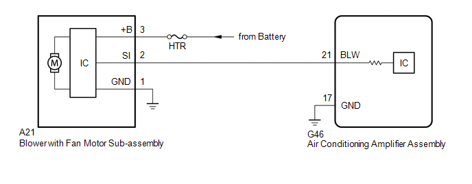
The blower with fan motor sub-assembly reads the signal from the air conditioning amplifier assembly and controls operation and speed changes of the blower motor.
If the blower air volume is weak, or there are any other blower malfunctions such as the temperature or air volume cannot be changed, the following causes are possible.
|
Malfunction Status |
Factor |
|---|---|
|
|
|
WIRING DIAGRAM
CAUTION / NOTICE / HINT
NOTICE:
Inspect the fuses for circuits related to this system before performing the following procedure.
PROCEDURE
PROCEDURE
|
1. |
PERFORM ACTIVE TEST USING TECHSTREAM (BLOWER MOTOR) |
(a) Connect the Techstream to the DLC3.
(b) Turn the ignition switch to ON.
(c) Turn the Techstream on.
(d) Enter the following menus: Body Electrical / Air Conditioner / Active Test.
(e) Perform the Active Test according to the display on the Techstream.
Body Electrical > Air Conditioner > Active Test
|
Tester Display |
Measurement Item |
Control Range |
Diagnostic Note |
|---|---|---|---|
|
Blower Motor |
Blower with fan motor sub-assembly |
Min.: 0 Max.: 31 |
- |
Body Electrical > Air Conditioner > Active Test
|
Tester Display |
|---|
|
Blower Motor |
OK:
Blower with fan motor sub-assembly is operated.
| NG |

|
|

|
2. |
CHECK HARNESS AND CONNECTOR (BLOWER WITH FAN MOTOR SUB-ASSEMBLY - BATTERY AND BODY GROUND) |
|
(a) Disconnect the blower with fan motor sub-assembly connector. |
|
(b) Measure the resistance according to the value(s) in the table below.
Standard Resistance:
|
Tester Connection |
Condition |
Specified Condition |
|---|---|---|
|
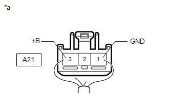
A21-1 (GND) - Body ground |
Always |
Below 1 Ω |
(c) Measure the voltage according to the value(s) in the table below.
Standard Voltage:
|
Tester Connection |
Condition |
Specified Condition |
|---|---|---|
|
A21-3 (+B) - Body ground |
Always |
11 to 14 V |
| NG |
|
REPAIR OR REPLACE HARNESS OR CONNECTOR |
|
|
3. |
CHECK HARNESS AND CONNECTOR (AIR CONDITIONING AMPLIFIER ASSEMBLY - BLOWER WITH FAN MOTOR SUB-ASSEMBLY) |
(a) Disconnect the G46 air conditioning amplifier assembly connector.
(b) Disconnect the A21 blower with fan motor sub-assembly connector.
(c) Measure the resistance according to the value(s) in the table below.
Standard Resistance:
|
Tester Connection |
Condition |
Specified Condition |
|---|---|---|
|
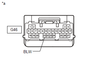
G46-21 (BLW) - A21-2 (SI) |
Always |
Below 1 Ω |
|
G46-21 (BLW) or A21-2 (SI) - Other terminals and body ground |
Always |
10 kΩ or higher |
| NG |
|
REPAIR OR REPLACE HARNESS OR CONNECTOR |
|
|
4. |
CHECK BLOWER WITH FAN MOTOR SUB-ASSEMBLY |
|
(a) Disconnect the air conditioning amplifier assembly connector. |
|
(b) Measure the voltage according to the value(s) in the table below.
Standard Voltage:
|
Tester Connection |
Condition |
Specified Condition |
|---|---|---|
|
G46-21 (BLW) - Body ground |
Always |
4.75 to 5.25 V |
| NG |
|
|
|
5. |
CHECK AIR CONDITIONING AMPLIFIER ASSEMBLY |
|
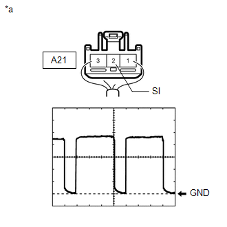
(a) Using the oscilloscope, check for the waveform.
HINT: The waveform varies with the blower speed. OK: Waveform is similar to that shown in the illustration. |
|
| OK |
|
| NG |
|
|
|
|