| Last Modified: 01-30-2024 | 6.11:8.1.0 | Doc ID: RM100000001FHNZ |
| Model Year Start: 2019 | Model: RAV4 | Prod Date Range: [11/2018 - ] |
| Title: A25A-FKS (FUEL): FUEL SENDER GAUGE ASSEMBLY (w/ Canister Pump Module): INSTALLATION; 2019 - 2024 MY RAV4 [11/2018 - ] | ||
INSTALLATION
PROCEDURE
1. INSTALL NO. 2 FUEL SENDER GAUGE ASSEMBLY
(a) Attach the claw and install the No. 2 fuel sender gauge assembly.
(b) Attach the 2 clamps and connect the wire harness to the fuel tank vent tube assembly.
(c) Connect the connector to the fuel tank vent tube assembly.
2. INSTALL FUEL TANK VENT TUBE ASSEMBLY
(a) Install a new gasket to the fuel tank assembly.
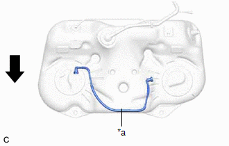
(b) Connect the fuel return vent tube sub-assembly and set the fuel tank vent tube assembly to the fuel tank assembly.
NOTICE:
Be careful not to bend the arm of the fuel sender gauge assembly.
NOTICE:
- Make sure to correctly assemble the fuel return vent tube sub-assembly as shown in the illustration. If assembled incorrectly, the fuel sender gauge assembly (No. 2 fuel sender gauge assembly) may catch on the fuel return vent tube resulting in incorrect operation of the fuel sender gauge assembly (No. 2 fuel sender gauge assembly) and an incorrect value being displayed on the fuel gauge.
- Be careful not to bend the arm of the fuel sender gauge assembly.
|
*a |
Fuel Return Vent Tube Sub-assembly |

|
Front of the Vehicle |
|
(c) Align the protrusions of the fuel tank vent tube assembly with the notches in the fuel tank assembly. |
|
3. INSTALL FUEL PUMP GAUGE RETAINER
(a) Install the fuel pump gauge retainer.
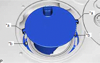
(1) While pressing down on the fuel tank vent tube assembly, temporarily install the fuel pump gauge retainer.
|
(2) Temporarily install SST (plate) and SST (claw) to the fuel pump gauge retainer. SST: 09808-14031 09808-01030 09808-01090 SST: 09808-01071 HINT: Securely insert the ends of SST (claw) into the insertion points in the fuel pump gauge retainer. |
|
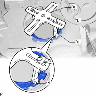
(3) While firmly pressing SST (claw) into the insertion points in the fuel pump gauge retainer, tighten SST (bolt).
|
(4) Install SST (handle) to SST (plate). SST: 09808-14031 09808-01010 09808-01030 09808-01090 SST: 09808-01071 |
|
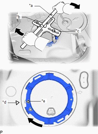
(5) Using SST, rotate the fuel pump gauge retainer so that the triangle mark on the fuel pump gauge retainer is aligned with the triangle mark on the fuel tank assembly to install the fuel tank vent tube assembly to the fuel tank assembly.
NOTICE:
- Do not use any tools other than specified as this may result in damage to the fuel pump gauge retainer or fuel tank assembly.
- Do not press down on SST excessively as this may make the fuel pump gauge retainer hard to rotate, and may damage components.
- Make sure to rotate SST (handle) horizontally. If it is rotated at an angle, SST may come off.
- Do not spin SST too fast or use an impact wrench as this may result in damage to components.
- If SST comes off of the fuel pump gauge retainer, loosen SST (bolt) and reinstall SST.
- Make sure that the fuel suction tube set gasket does not come off.
(b) Attach the claw and install the No. 1 fuel tube clamp to the fuel pump gauge retainer.
4. INSTALL REAR FLOOR SERVICE HOLE COVER (for RH Side)
(a) Remove any remaining butyl tape from the rear floor service hole cover and body.
(b) Connect the connector to the fuel tank vent tube assembly.
(c) Install the rear floor service hole cover with new butyl tape.
NOTICE:
Securely install the rear floor service hole cover.
5. INSTALL FUEL SENDER GAUGE ASSEMBLY
(a) Attach the 2 claws and install the fuel sender gauge assembly.
(b) Attach the clamp and connect the wire harness.
NOTICE:
Do not damage the wire harness.
(c) Attach the 2 clamps and connect the wire harness.
NOTICE:
Do not damage the wire harness.
(d) Connect the 2 connectors to the fuel suction plate sub-assembly.
6. INSTALL FUEL SUCTION WITH PUMP AND GAUGE TUBE ASSEMBLY
Click here
![2019 - 2024 MY RAV4 [11/2018 - ]; A25A-FKS (FUEL): FUEL PUMP (w/ Canister Pump Module): INSTALLATION](/t3Portal/stylegraphics/info.gif)
7. CONNECT CABLE TO NEGATIVE BATTERY TERMINAL
NOTICE:
When disconnecting the cable, some systems need to be initialized after the cable is reconnected.
Click here
|
|
|