| Last Modified: 05-08-2025 | 6.11:8.1.0 | Doc ID: RM100000001FHCP |
| Model Year Start: 2019 | Model: RAV4 | Prod Date Range: [11/2018 - 02/2019] |
| Title: AXLE AND DIFFERENTIAL: FRONT AXLE HUB BOLT: REPLACEMENT; 2019 MY RAV4 RAV4 HV [11/2018 - 02/2019] | ||
REPLACEMENT
CAUTION / NOTICE / HINT
The necessary procedures (adjustment, calibration, initialization, or registration) that must be performed after parts are removed and installed, or replaced during front axle hub bolt removal/installation are shown below.
Necessary Procedures After Parts Removed/Installed/Replaced (for HV Model:)
|
Replaced Part or Performed Procedure |
Necessary Procedures |
Effect/Inoperative Function When Necessary Procedures are not Performed |
Link |
|---|---|---|---|
|
Auxiliary battery terminal is disconnected/reconnected |
Perform steering sensor zero point calibration |
Lane control system |
|
|
Pre-collision system |
|||
|
Memorize steering angle neutral point |
Parking assist monitor system |
|
|
|
Panoramic view monitor system (for HV model) |
|
||
|
Reset back door close position |
Power back door system (for HV model) |
|
|
|
Back door lock initialization |
Power door lock control system |
|
NOTICE:
After the ignition switch is turned off, the radio and display receiver assembly records various types of memory and settings. As a result, after turning the ignition switch off, be sure to wait for the time specified in the following table before disconnecting the cable from the negative (-) auxiliary battery terminal.
Waiting Time before Disconnecting Cable from Negative (-) Auxiliary Battery Terminal
|
System Name |
See Procedure |
|---|---|
|
Vehicle enrolled in Toyota Entune system or safety connect system |
6 minutes |
|
Vehicle not enrolled in Toyota Entune system and safety connect system |
1 minute |
HINT:
- Use the same procedure for the RH and LH sides.
- The following procedure is for the LH side.
PROCEDURE
1. DISABLE BRAKE CONTROL (w/o Vacuum Brake Booster)
Click here
![2019 MY RAV4 RAV4 HV [11/2018 - 02/2019]; BRAKE (REAR): REAR BRAKE: REMOVAL+](/t3Portal/stylegraphics/info.gif)
2. REMOVE FRONT WHEEL
Click here
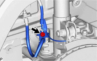
3. DISCONNECT FRONT FLEXIBLE HOSE
|
(a) Remove the bolt and disconnect the front flexible hose from the front shock absorber assembly. |
|
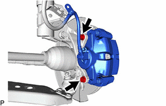
4. DISCONNECT FRONT DISC BRAKE CALIPER ASSEMBLY LH
|
(a) Remove the 2 bolts and disconnect the front disc brake caliper assembly from the steering knuckle. NOTICE: Use wire or an equivalent tool to keep the front disc brake caliper assembly from hanging by the front flexible hose. |
|
5. REMOVE FRONT DISC
Click here
6. REMOVE FRONT AXLE HUB BOLT LH
|
(a) Temporarily install 2 service nuts to the front axle hub bolts as shown in the illustration. Recommended service nut: Thread diameter: 12.0 mm (0.472 in.) Thread pitch: 1.5 mm (0.0591 in.) NOTICE: Install the service nuts to prevent damage to the front axle hub bolts. |
|
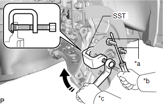
(b) Using SST and a screwdriver or an equivalent tool to hold the front axle hub sub-assembly, remove the front axle hub bolt.
SST: 09650-17011
NOTICE:
Do not damage the threads of the front axle hub bolts.
7. INSTALL FRONT AXLE HUB BOLT LH
(a) Temporarily install a new front axle hub bolt to the front axle hub sub-assembly.
|
(b) Install a washer and service nut to the front axle hub bolt as shown in the illustration. Recommended service nut: Thread diameter: 12.0 mm (0.472 in.) Thread pitch: 1.5 mm (0.0591 in.) HINT: Recommended washer thickness is 5 mm (0.197 in.) or more. |
|
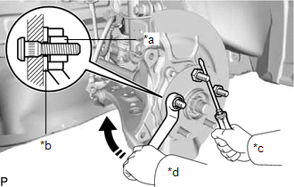
(c) Using a screwdriver or an equivalent tool to hold the front axle hub sub-assembly, install the front axle hub bolt by tightening the service nut.
NOTICE:
- Install the service nuts to prevent damage to the front axle hub bolts.
- Do not damage the threads of the front axle hub bolts.
(d) Remove the 3 service nuts and washer from the 3 front axle hub bolts.
8. INSTALL FRONT DISC
Click here
9. INSTALL FRONT DISC BRAKE CALIPER ASSEMBLY LH
|
(a) Install the front disc brake caliper assembly to the steering knuckle with the 2 bolts. Torque: for Steel Steering Knuckle : 107 N·m {1091 kgf·cm, 79 ft·lbf} for Aluminum Steering Knuckle : 150 N·m {1530 kgf·cm, 111 ft·lbf} NOTICE:
|
|
10. CONNECT FRONT FLEXIBLE HOSE
(a) Set the 2 front speed sensor LH hooks on the front shock absorber assembly LH.
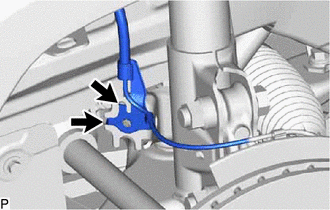

|
Hook |
NOTICE:
Do not twist the front speed sensor when installing it.
|
(b) Connect the front speed sensor and front flexible hose to the front shock absorber assembly with the bolt. Torque: 29 N·m {296 kgf·cm, 21 ft·lbf} NOTICE: Do not twist the front flexible hose when installing it. |
|
11. INSTALL FRONT WHEEL
Click here
12. CONNECT CABLE TO NEGATIVE AUXILIARY BATTERY TERMINAL (w/o Vacuum Brake Booster)
(a) Connect the reservoir level switch connector.
(b) Connect the cable to the negative (-) auxiliary battery terminal.
Click here
(c) Perform the following procedure if air bleeding is not necessary:
(1) Turn the ignition switch on (READY).
(2) Depress the brake pedal and release it.
(3) Clear the DTCs.
Click here
|
|
|