| Last Modified: 01-30-2024 | 6.11:8.1.0 | Doc ID: RM100000001FH3U |
| Model Year Start: 2019 | Model: RAV4 | Prod Date Range: [11/2018 - ] |
| Title: A25A-FKS (ENGINE MECHANICAL): CYLINDER HEAD: INSPECTION; 2019 - 2024 MY RAV4 [11/2018 - ] | ||
INSPECTION
PROCEDURE
1. INSPECT CYLINDER HEAD SUB-ASSEMBLY
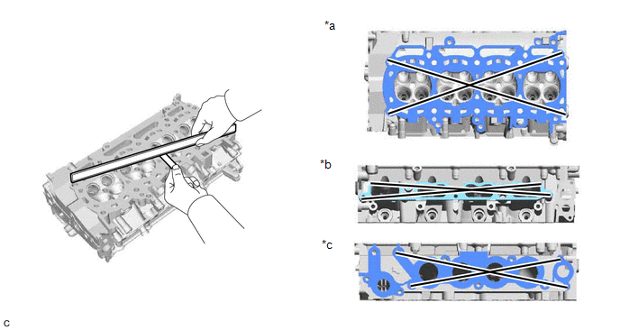
(a) Using a precision straightedge and feeler gauge, measure the warpage of the contact surfaces where the cylinder head sub-assembly contacts the cylinder block sub-assembly, intake manifold and exhaust manifold.
|
*a |
Bottom Side |
*b |
Intake Manifold Side |
|
*c |
Exhaust Manifold Side |
- |
- |
Maximum Warpage:
|
Item |
Specified Condition |
|---|---|
|
Bottom side |
0.05 mm (0.00197 in.) |
|
Intake manifold side |
0.10 mm (0.00394 in.) |
|
Exhaust manifold side |
0.10 mm (0.00394 in.) |
HINT:
If the warpage is more than the maximum, replace the cylinder head sub-assembly.
|
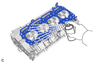
(b) Using a dye penetrant, check the intake ports, exhaust ports and cylinder head sub-assembly surface for cracks. HINT: If cracks are found, replace the cylinder head sub-assembly. |
|
2. INSPECT INTAKE VALVE COMPRESSION SPRING
|
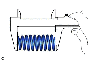
(a) Using a vernier caliper, measure the free length of the intake valve compression spring. Standard Free Length: 53.71 mm (2.11 in.) NOTICE: Intake valve compression springs come in 2 different lengths. Make sure all intake valve compression springs are the same length when replacing them. |
|
|
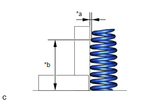
(b) Using a steel square, measure the deviation of the intake valve compression spring. Maximum Deviation (Reference): 1.0 mm (0.0394 in.) HINT: If the deviation is more than the maximum, replace the intake valve compression spring. |
|
3. INSPECT EXHAUST VALVE COMPRESSION SPRING
|
(a) Using a vernier caliper, measure the free length of the exhaust valve compression spring. Standard Free Length: 55.11 mm (2.17 in.) NOTICE: Exhaust valve compression springs come in 2 different lengths. Make sure all exhaust valve compression springs are the same length when replacing them. |
|
|
(b) Using a steel square, measure the deviation of the exhaust valve compression spring. Maximum Deviation (Reference): 1.0 mm (0.0394 in.) HINT: If the deviation is more than the maximum, replace the exhaust valve compression spring. |
|
4. INSPECT INTAKE VALVE
|
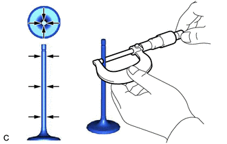
(a) Using a micrometer, measure the diameter of the valve stem. Standard Valve Stem Diameter: 5.470 to 5.485 mm (0.215 to 0.216 in.) HINT: If the valve stem diameter is not as specified, check the intake valve guide bush oil clearance. |
|
|
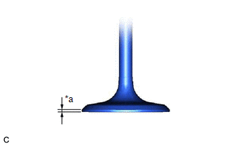
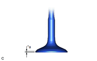
(b) Using a vernier caliper, measure the valve head margin thickness. Standard Margin Thickness: 1.0 mm (0.0394 in.) Minimum Margin Thickness: 0.5 mm (0.0197 in.) HINT: If the margin thickness is less than the minimum, replace the intake valve. |
|
|
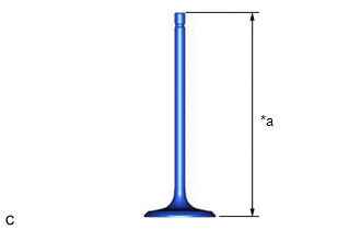
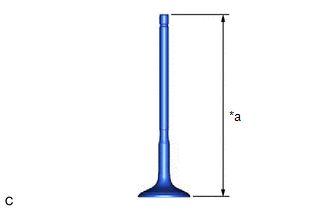
(c) Using a vernier caliper, measure the overall length of the intake valve. Standard Overall Length: 104.45 mm (4.11 in.) Minimum Overall Length: 103.95 mm (4.09 in.) HINT: If the overall length is less than the minimum, replace the intake valve. |
|
5. INSPECT EXHAUST VALVE
|
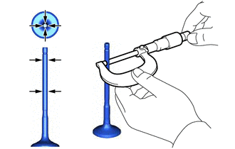
(a) Using a micrometer, measure the diameter of the valve stem. Standard Valve Stem Diameter: 5.465 to 5.480 mm (0.215 to 0.216 in.) HINT: If the valve stem diameter is not as specified, check the exhaust valve guide bush oil clearance. |
|
|
(b) Using a vernier caliper, measure the valve head margin thickness. Standard Margin Thickness: 1.0 mm (0.0394 in.) Minimum Margin Thickness: 0.5 mm (0.0197 in.) HINT: If the margin thickness is less than the minimum, replace the exhaust valve. |
|
|
(c) Using a vernier caliper, measure the overall length of the exhaust valve. Standard Overall Length: 108.7 mm (4.28 in.) Minimum Overall Length: 108.2 mm (4.26 in.) HINT: If the overall length is less than the minimum, replace the exhaust valve. |
|
6. INSPECT VALVE GUIDE BUSH OIL CLEARANCE
|
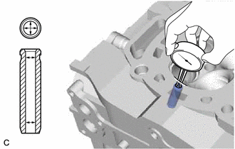
(a) Using a caliper gauge, measure the inside diameter of the valve guide bush. Standard Valve Guide Bush Inside Diameter: 5.51 to 5.53 mm (0.217 to 0.218 in.) |
|
(b) Subtract the valve stem diameter measurement from the valve guide bush inside diameter measurement.
Standard Oil Clearance:
|
Item |
Specified Condition |
|---|---|
|
Intake Side |
0.025 to 0.060 mm (0.000984 to 0.00236 in.) |
|
Exhaust Side |
0.030 to 0.065 mm (0.00118 to 0.00256 in.) |
Maximum Oil Clearance:
|
Item |
Specified Condition |
|---|---|
|
Intake Side |
0.080 mm (0.00315 in.) |
|
Exhaust Side |
0.10 mm (0.00394 in.) |
HINT:
- Oil clearance = Valve guide bush inside diameter - Valve stem diameter
- If the oil clearance is more than the maximum, replace the valve and valve guide bush.
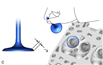
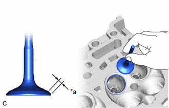
7. INSPECT INTAKE VALVE SEAT
(a) Apply a light coat of Prussian blue to the valve face.
|
(b) Lightly press the valve face against the intake valve seat. NOTICE: Do not rotate the valve while pressing it. |
|
(c) Check the valve face and intake valve seat by using the following procedure:
(1) If Prussian blue appears 360° around the entire intake valve face, the valve face is concentric.
HINT:
If the valve face is not concentric, replace the intake valve.
(2) If Prussian blue appears 360° around the entire intake valve seat, the intake valve seat and valve face are concentric.
HINT:
If the valve face is not concentric, resurface the intake valve seat.
(3) Measure the width of the contact area of the intake valve seat and valve face.
Standard Width:
1.0 to 1.4 mm (0.0394 to 0.0551 in.)
8. INSPECT EXHAUST VALVE SEAT
(a) Apply a light coat of Prussian blue to the valve face.
|
(b) Lightly press the valve face against the exhaust valve seat. NOTICE: Do not rotate the valve while pressing it. |
|
(c) Check the valve face and exhaust valve seat by using the following procedure:
(1) If Prussian blue appears 360° around the entire exhaust valve face, the valve face is concentric.
HINT:
If the valve face is not concentric, replace the exhaust valve.
(2) If Prussian blue appears 360° around the entire exhaust valve seat, the exhaust valve seat and valve face are concentric.
HINT:
If the valve face is not concentric, resurface the exhaust valve seat.
(3) Measure the width of the contact area of the exhaust valve seat and valve face.
Standard Width:
1.3 to 1.7 mm (0.0512 to 0.0669 in.)
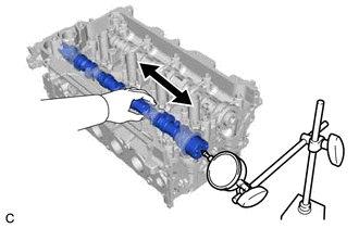
9. INSPECT CAMSHAFT THRUST CLEARANCE
(a) Clean the No. 1 camshaft bearing cap, No. 2 camshaft bearing cap, 2 No. 3 camshaft bearing caps, No. 4 camshaft bearing cap, camshaft housing sub-assembly and camshaft journals.
(b) Place the camshaft and No. 2 camshaft on the camshaft housing sub-assembly on the cylinder head sub-assembly.
(c) Install the camshaft bearing caps.
Click here
![2019 - 2020 MY RAV4 [11/2018 - 06/2020]; A25A-FKS (ENGINE MECHANICAL): ENGINE UNIT: REASSEMBLY+](/t3Portal/stylegraphics/info.gif)
(d) Install the camshaft housing sub-assembly.
Click here
|
(e) Using a dial indicator, measure the thrust clearance while moving the camshaft and No. 2 camshaft back and forth. Standard Thrust Clearance:
Maximum Thrust Clearance:
HINT: If the thrust clearance is more than the maximum, replace the camshaft housing sub-assembly. If the thrust surface is damaged, replace the camshaft. |
|
|
|
|