- DTC judgment completed
- System normal
| Last Modified: 01-30-2024 | 6.11:8.1.0 | Doc ID: RM100000001FDUF |
| Model Year Start: 2019 | Model: RAV4 | Prod Date Range: [11/2018 - 08/2020] |
| Title: A25A-FKS (ENGINE CONTROL): SFI SYSTEM (w/ Canister Pump Module): P0A1412; Engine Mount "A" Control Circuit High Circuit Short to Battery; 2019 - 2020 MY RAV4 [11/2018 - 08/2020] | ||
|
DTC |
P0A1412 |
Engine Mount "A" Control Circuit High Circuit Short to Battery |
DESCRIPTION
|
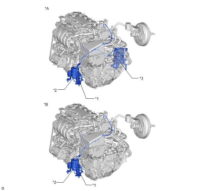
*A |
for 2WD |
*B |
for AWD |
|
*1 |
Vacuum Switching Valve (for Active Control Engine Mount System) |
*2 |
Front Engine Mounting Insulator |
|
*3 |
Rear Engine Mounting Insulator |
- |
- |
The active control engine mount system decreases engine vibration at a low engine speed using the vacuum switching valve (for active control engine mount system). The vacuum switching valve (for active control engine mount system) is controlled by a pulse signal transmitted to the vacuum switching valve (for active control engine mount system) from the ECM. The frequency of this pulse signal is matched to the engine speed to decrease engine vibration.
|
DTC No. |
Detection Item |
DTC Detection Condition |
Trouble Area |
MIL |
Memory |
Note |
|---|---|---|---|---|---|---|
|
P0A1412 |
Engine Mount "A" Control Circuit High Circuit Short to Battery |
Short in vacuum switching valve (for active control engine mount system) circuit and power supply circuit (2 trip detection logic). |
|
Does not come on |
DTC stored |
SAE Code: P0A16 |
MONITOR DESCRIPTION
The ECM monitors the output voltage while the vacuum switching valve (for active control engine mount system) is operating.
The vacuum switching valve (for active control engine mount system) turns on and off according to ON/OFF switching of a transistor inside the ECM.
If a continuous mismatch occurs between the ECM transistor state and the output voltage, the ECM determines there is a malfunction in the vacuum switching valve (for active control engine mount system) circuit and stores a DTC.
MONITOR STRATEGY
|
Frequency of Operation |
Continuous |
CONFIRMATION DRIVING PATTERN
- Connect the Techstream to the DLC3.
- Turn the ignition switch to ON.
- Turn the Techstream on.
- Clear the DTCs (even if no DTCs are stored, perform the clear DTC procedure).
- Turn the ignition switch off and wait for at least 30 seconds.
- Turn the ignition switch to ON.
- Turn the Techstream on.
- Enter the following menus: Powertrain / Engine / Active Test / Activate the ACM Inhibit.
- In the Active Test, wait for at least 5 seconds with the vacuum switching valve (for active control engine mount system) at ON.
- In the Active Test, wait for at least 5 seconds with the vacuum switching valve (for active control engine mount system) at OFF.
- Enter the following menus: Powertrain / Engine / Trouble Codes.
-
Read the pending DTCs.
HINT:
- If a pending DTC is output, the system is malfunctioning.
- If a pending DTC is not output, perform the following procedure.
- Enter the following menus: Powertrain / Engine / Utility / All Readiness.
- Input the DTC: P0A1412.
-
Check the DTC judgment result.
Techstream Display
Description
NORMAL
ABNORMAL
- DTC judgment completed
- System abnormal
INCOMPLETE
- DTC judgment not completed
- Perform driving pattern after confirming DTC enabling conditions
HINT:
- If the judgment result is NORMAL, the system is normal.
- If the judgment result is ABNORMAL, the system has a malfunction.
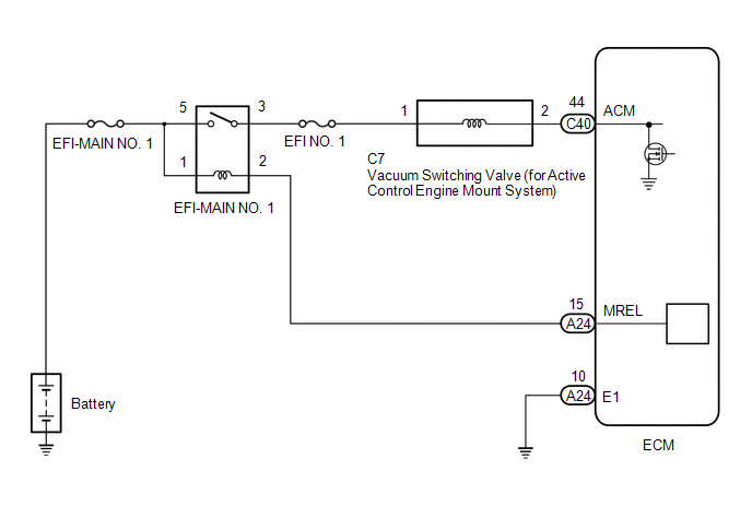
WIRING DIAGRAM
CAUTION / NOTICE / HINT
HINT:
Read Freeze Frame Data using the Techstream. The ECM records vehicle and driving condition information as Freeze Frame Data the moment a DTC is stored. When troubleshooting, Freeze Frame Data can help determine if the vehicle was moving or stationary, if the engine was warmed up or not, if the air fuel ratio was lean or rich, and other data from the time the malfunction occurred.
PROCEDURE
|
1. |
INSPECT VACUUM SWITCHING VALVE (FOR ACTIVE CONTROL ENGINE MOUNT SYSTEM) |
(a) Inspect the vacuum switching valve (for active control engine mount system).
Click here
![2019 - 2024 MY RAV4 [11/2018 - ]; A25A-FKS (ENGINE CONTROL): VACUUM SWITCHING VALVE (for Engine Mounting): INSPECTION](/t3Portal/stylegraphics/info.gif)
| NG |

|
REPLACE VACUUM SWITCHING VALVE (FOR ACTIVE CONTROL ENGINE MOUNT SYSTEM) |
|

|
2. |
CHECK HARNESS AND CONNECTOR (VACUUM SWITCHING VALVE (FOR ACTIVE CONTROL ENGINE MOUNT SYSTEM) - ECM) |
(a) Disconnect the vacuum switching valve (for active control engine mount system) connector.
(b) Disconnect the ECM connector.
(c) Measure the resistance according to the value(s) in the table below.
Standard Resistance:
|
Tester Connection |
Condition |
Specified Condition |
|---|---|---|
|
C7-2 or C40-44 (ACM) - Other terminals |
Always |
10 kΩ or higher |
| OK |
|
| NG |
|
REPAIR OR REPLACE HARNESS OR CONNECTOR |
|
|
|