- Replacement of throttle body assembly
- Cleaning the deposits from the throttle body assembly
- Replacement of EGR valve assembly
- Gas leak from exhaust system is repaired
| Last Modified: 01-30-2024 | 6.11:8.1.0 | Doc ID: RM100000001FC4O |
| Model Year Start: 2019 | Model: RAV4 | Prod Date Range: [11/2018 - 02/2019] |
| Title: A25A-FKS (INTAKE / EXHAUST): INTAKE MANIFOLD: REMOVAL; 2019 MY RAV4 [11/2018 - 02/2019] | ||
REMOVAL
CAUTION / NOTICE / HINT
The necessary procedures (adjustment, calibration, initialization or registration) that must be performed after parts are removed and installed, or replaced during intake manifold removal/installation are shown below.
Necessary Procedures After Parts Removed/Installed/Replaced
|
Replaced Part or Performed Procedure |
Necessary Procedure |
Effect/Inoperative Function when Necessary Procedure not Performed |
Link |
|---|---|---|---|
|
|
Inspection After Repair |
|
|
NOTICE:
This procedure includes the removal of small-head bolts. Refer to Small-Head Bolts of Basic Repair Hint to identify the small-head bolts.
Click here
![2019 - 2024 MY RAV4 RAV4 HV [11/2018 - ]; INTRODUCTION: REPAIR INSTRUCTION: PRECAUTION](/t3Portal/stylegraphics/info.gif)
PROCEDURE
1. REMOVE THROTTLE BODY WITH MOTOR ASSEMBLY
Click here
2. REMOVE EGR VALVE ASSEMBLY
Click here
3. REMOVE E.F.I. VACUUM SENSOR ASSEMBLY (MANIFOLD ABSOLUTE PRESSURE SENSOR)
Click here
4. DISCONNECT ENGINE WIRE
|
(a) Remove the bolt. |
|
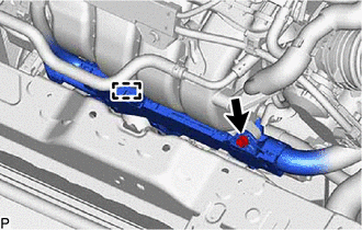
(b) Detach the wire harness clamp and disconnect the engine wire.
5. REMOVE NO. 2 WATER BY-PASS PIPE
|
(a) Using an 8 mm socket wrench, remove the 2 bolts (A) and disconnect the No. 2 water by-pass pipe from the intake manifold. |
|
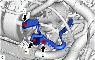
(b) Remove the bolt (B) and No. 2 water by-pass pipe from the cylinder block sub-assembly.
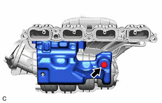
6. DISCONNECT NO. 3 WATER BY-PASS PIPE
|
(a) Slide the clip and disconnect the No. 5 water by-pass hose from the No. 3 water by-pass pipe. |
|
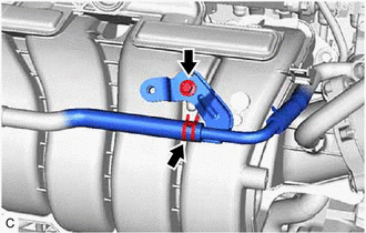
(b) Using an 8 mm socket wrench, remove the bolt and disconnect the No. 3 water by-pass pipe from the intake manifold.
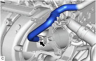
7. DISCONNECT NO. 2 FUEL VAPOR FEED HOSE
|
(a) Disconnect the No. 2 fuel vapor feed hose from the intake manifold. |
|
8. REMOVE INTAKE MANIFOLD
|
(a) w/o Stud Bolt: (1) Remove the 5 bolts and intake manifold from the cylinder head sub-assembly. |
|

(b) w/ Stud Bolt:
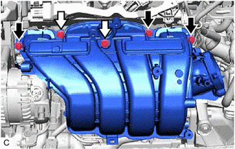

|
Bolt |

|
Nut |
(1) Remove the 3 bolts, 2 nuts and intake manifold from the cylinder head sub-assembly.
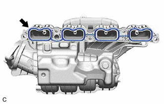
9. REMOVE NO. 1 INTAKE MANIFOLD TO HEAD GASKET
|
(a) Remove the No. 1 intake manifold to head gasket from the intake manifold. |
|
10. REMOVE NO. 1 ENGINE COVER
|
(a) Remove the clip and No. 1 engine cover. |
|
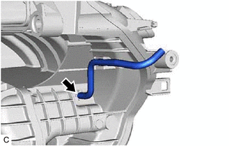
11. REMOVE VACUUM HOSE
|
(a) Remove the vacuum hose from the intake manifold. |
|
|
|
|