- Short to ground in PIM circuit
- Short in PIM to EPIM circuit
- Open in VCPM circuit
| Last Modified: 01-30-2024 | 6.11:8.1.0 | Doc ID: RM100000001F4SS |
| Model Year Start: 2019 | Model: RAV4 | Prod Date Range: [11/2018 - 08/2020] |
| Title: A25A-FKS (ENGINE CONTROL): SFI SYSTEM (w/ Canister Pump Module): P010511; Manifold Absolute Pressure / Barometric Pressure Sensor Circuit Short to Ground; 2019 - 2020 MY RAV4 [11/2018 - 08/2020] | ||
|
DTC |
P010511 |
Manifold Absolute Pressure / Barometric Pressure Sensor Circuit Short to Ground |
DESCRIPTION
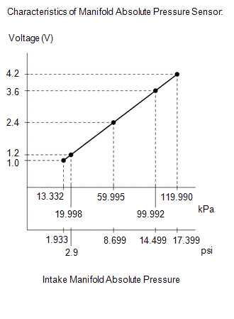
The manifold absolute pressure sensor detects the intake manifold pressure as a change in voltage. The ECM calculates the intake manifold pressure based on this voltage. The ECM calculates the EGR valve assembly and purge VSV opening amount according to changes in the intake manifold pressure and also detects malfunctions of the manifold absolute pressure sensor using these changes in pressure.
|
DTC No. |
Detection Item |
DTC Detection Condition |
Trouble Area |
MIL |
Memory |
Note |
|---|---|---|---|---|---|---|
|
P010511 |
Manifold Absolute Pressure / Barometric Pressure Sensor Circuit Short to Ground |
The manifold absolute pressure sensor output voltage is less than 0.5 V for 0.5 seconds or more (1 trip detection logic). |
|
Comes on |
DTC stored |
SAE Code: P0107 |
HINT:
When this DTC is output, check the intake manifold absolute pressure in the Data List. Enter the following menus: Powertrain / Engine / Data List / Intake Manifold Absolute Pressure.
|
DTC No. |
Intake Manifold Absolute Pressure |
Malfunction |
|---|---|---|
|
P010511 |
Approximately 0 kPa (0 psi) |
|
If the Data List value is normal it may be due to a temporary recovery from the malfunction condition. Check for intermittent problems.
Click here
![2019 - 2020 MY RAV4 [11/2018 - 08/2020]; A25A-FKS (ENGINE CONTROL): SFI SYSTEM (w/ Canister Pump Module): CHECK FOR INTERMITTENT PROBLEMS](/t3Portal/stylegraphics/info.gif)
MONITOR DESCRIPTION
The ECM monitors the manifold absolute pressure sensor voltage and uses this value to calculate the intake manifold pressure. When the manifold absolute pressure sensor output voltage deviates from the normal operating range, the ECM interprets this as a malfunction in the manifold absolute pressure sensor circuit, illuminates the MIL and stores a DTC.
Example:
If the manifold absolute pressure sensor output voltage is less than 0.5 V for 0.5 seconds or more, the ECM stores this DTC.
MONITOR STRATEGY
|
Related DTCs |
P0107: Manifold absolute pressure sensor range check (low voltage) |
|
Required Sensors/Components (Main) |
Manifold absolute pressure sensor |
|
Required Sensors/Components (Related) |
- |
|
Frequency of Operation |
Continuous |
|
Duration |
0.5 seconds |
|
MIL Operation |
Immediate |
|
Sequence of Operation |
None |
TYPICAL ENABLING CONDITIONS
|
Monitor runs whenever the following DTCs are not stored |
None |
|
All of the following conditions are met |
- |
|
Battery voltage |
8 V or higher |
|
Ignition switch |
ON |
|
Time after ignition switch off to ON |
0.5 seconds or more |
|
Time after starter on to off |
0.5 seconds or more |
TYPICAL MALFUNCTION THRESHOLDS
|
Manifold absolute pressure sensor voltage (Manifold absolute pressure) |
Less than 0.5 V (Less than 0 kPa(abs) [0 psi(abs)]) |
CONFIRMATION DRIVING PATTERN
HINT:
-
After repair has been completed, clear the DTC and then check that the vehicle has returned to normal by performing the following All Readiness check procedure.
Click here
-
When clearing the permanent DTCs, refer to the "CLEAR PERMANENT DTC" procedure.
Click here
- Connect the Techstream to the DLC3.
- Turn the ignition switch to ON.
- Turn the Techstream on.
- Clear the DTCs (even if no DTCs are stored, perform the clear DTC procedure).
- Turn the ignition switch off and wait for at least 30 seconds.
- Start the engine and wait 5 seconds or more [A].
- Turn the Techstream on.
- Enter the following menus: Powertrain / Engine / Trouble Codes [B].
-
Read the pending DTCs.
HINT:
- If a pending DTC is output, the system is malfunctioning.
- If a pending DTC is not output, perform the following procedure.
- Enter the following menus: Powertrain / Engine / Utility / All Readiness.
- Input the DTC: P010511.
-
Check the DTC judgment result.
Techstream Display
Description
NORMAL
- DTC judgment completed
- System normal
ABNORMAL
- DTC judgment completed
- System abnormal
INCOMPLETE
- DTC judgment not completed
- Perform driving pattern after confirming DTC enabling conditions
HINT:
- If the judgment result is NORMAL, the system is normal.
- If the judgment result is ABNORMAL, the system is malfunctioning.
-
[A] to [B]: Normal judgment procedure.
The normal judgment procedure is used to complete DTC judgment and also used when clearing permanent DTCs.
- When clearing the permanent DTCs, do not disconnect the cable from the battery terminal or attempt to clear the DTCs during this procedure, as doing so will clear the universal trip and normal judgment histories.
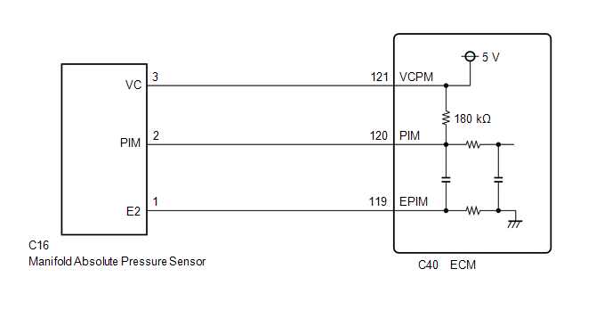
WIRING DIAGRAM
CAUTION / NOTICE / HINT
HINT:
Read Freeze Frame Data using the Techstream. The ECM records vehicle and driving condition information as Freeze Frame Data the moment a DTC is stored. When troubleshooting, Freeze Frame Data can help determine if the vehicle was moving or stationary, if the engine was warmed up or not, if the air fuel ratio was lean or rich, and other data from the time the malfunction occurred.
PROCEDURE
|
1. |
CHECK HARNESS AND CONNECTOR |
|
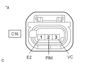
*a |
Front view of wire harness connector (to Manifold Absolute Pressure Sensor) |
HINT:
Make sure that the connector is properly connected. If it is not, securely connect it and check for DTCs again.
(a) Disconnect the manifold absolute pressure sensor connector.
(b) Turn the ignition switch to ON.
(c) Measure the voltage according to the value(s) in the table below.
Standard Voltage:
|
Tester Connection |
Condition |
Specified Condition |
|---|---|---|
|
C16-3 (VC) - C16-1 (E2) |
Ignition switch ON |
4.75 to 5.25 V |
|
C16-2 (PIM) - C16-1 (E2) |
Ignition switch ON |
1.2 to 5.25 V |
(d) Turn the ignition switch off and wait for at least 30 seconds.
(e) Measure the resistance according to the value(s) in the table below.
Standard Resistance:
|
Tester Connection |
Condition |
Specified Condition |
|---|---|---|
|
C16-3 (VC) - C16-2 (PIM) |
Ignition switch off |
171 to 189 kΩ |
| OK |

|
|

|
2. |
CHECK HARNESS AND CONNECTOR (MANIFOLD ABSOLUTE PRESSURE SENSOR - ECM) |
(a) Disconnect the manifold absolute pressure sensor connector.
(b) Disconnect the ECM connector.
(c) Measure the resistance according to the value(s) in the table below.
Standard Resistance:
|
Tester Connection |
Condition |
Specified Condition |
|---|---|---|
|
C16-3 (VC) - C40-121 (VCPM) |
Always |
Below 1 Ω |
|
C16-2 (PIM) or C40-120 (PIM) - Body ground and other terminals |
Always |
10 kΩ or higher |
| OK |
|
| NG |
|
REPAIR OR REPLACE HARNESS OR CONNECTOR |
|
|
|