| Last Modified: 01-30-2024 | 6.11:8.1.0 | Doc ID: RM100000001EVC1 |
| Model Year Start: 2019 | Model: RAV4 HV | Prod Date Range: [11/2018 - ] |
| Title: A25A-FXS (ENGINE CONTROL): RELAY: ON-VEHICLE INSPECTION; 2019 - 2024 MY RAV4 HV [11/2018 - ] | ||
ON-VEHICLE INSPECTION
PROCEDURE
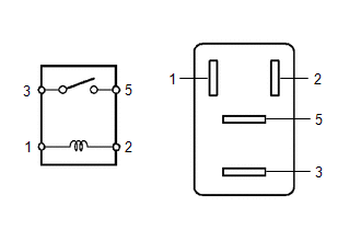
1. INSPECT NO. 1 ELECTRONIC FUEL INJECTION MAIN RELAY (EFI-MAIN NO. 1)
|
(a) Measure the resistance according to the value(s) in the table below. Standard Resistance:
If the result is not as specified, replace the No. 1 electronic fuel injection main relay (EFI-MAIN NO. 1). |
|
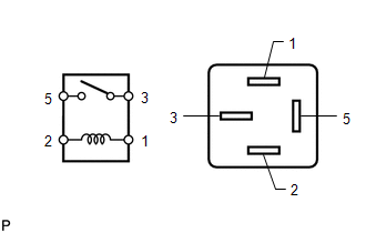
2. INSPECT NO. 2 ELECTRONIC FUEL INJECTION MAIN RELAY (EFI-MAIN NO. 2)
|
(a) Measure the resistance according to the value(s) in the table below. Standard Resistance:
If the result is not as specified, replace the No. 2 electronic fuel injection main relay (EFI-MAIN NO. 2). |
|
3. INSPECT NO. 3 ELECTRONIC FUEL INJECTION MAIN RELAY (EFI-MAIN NO. 3)
|
(a) Measure the resistance according to the value(s) in the table below. Standard Resistance:
If the result is not as specified, replace the No. 3 electronic fuel injection main relay (EFI-MAIN NO. 3). |
|
4. INSPECT ELECTRONIC DRIVER UNIT RELAY (D INJ)
|
(a) Measure the resistance according to the value(s) in the table below. Standard Resistance:
If the result is not as specified, replace the electronic driver unit relay (D INJ). |
|
5. INSPECT VVT RELAY (VVT)
|
(a) Measure the resistance according to the value(s) in the table below. Standard Resistance:
If the result is not as specified, replace the VVT relay (VVT). |
|
6. INSPECT NO. 2 IGNITION RELAY (IG2 NO. 1)
|
(a) Measure the resistance according to the value(s) in the table below. Standard Resistance:
If the result is not as specified, replace the No. 2 ignition relay (IG2 NO. 1). |
|
|
|
|