| Last Modified: 01-30-2024 | 6.11:8.1.0 | Doc ID: RM100000001ES5C |
| Model Year Start: 2019 | Model: RAV4 | Prod Date Range: [11/2018 - 10/2022] |
| Title: AUDIO / VIDEO: AUDIO AND VISUAL SYSTEM: C1622; Back Camera Disconnected; 2019 - 2022 MY RAV4 RAV4 HV [11/2018 - 10/2022] | ||
|
DTC |
C1622 |
Back Camera Disconnected |
DESCRIPTION
This DTC is stored if the radio and display receiver assembly judges that the signals or signal lines between the rear television camera assembly*1 or parking assist ECU*2 and the radio and display receiver assembly are not normal as a result of its self check.
|
DTC No. |
Detection Item |
DTC Detection Condition |
Trouble Area |
|---|---|---|---|
|
C1622 |
Back Camera Disconnected |
Open or Short Circuit in rear television camera signal |
|
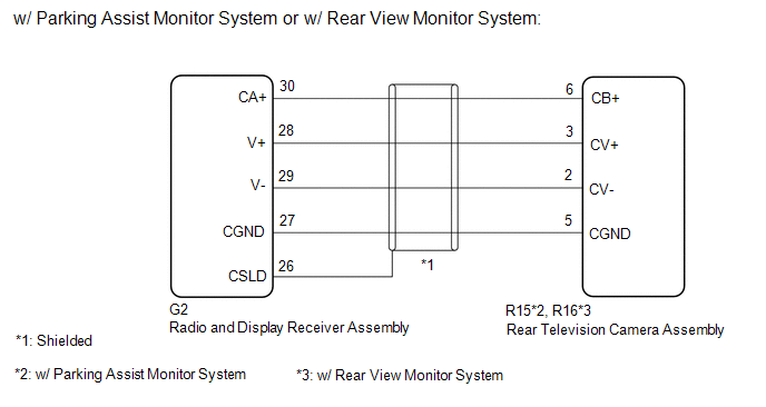
- *1: w/ Parking Assist Monitor System or w/ Rear View Monitor System
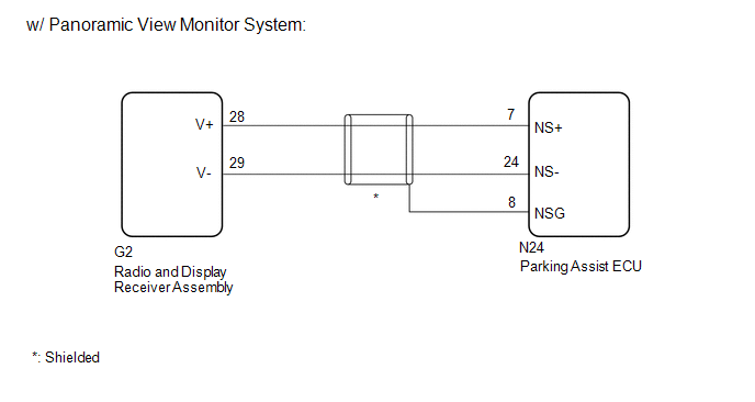
- *2: w/ Panoramic View Monitor System
WIRING DIAGRAM
PROCEDURE
|
1. |
CHECK MODEL |
(a) Choose the model to be inspected.
|
Result |
Proceed to |
|---|---|
|
w/ Parking Assist Monitor System or w/ Rear View Monitor System: |
A |
|
w/ Panoramic View Monitor System |
B |
| B |

|
|

|
2. |
CHECK FOR DTC |
(a) Clear the DTCs.
Click here
![2019 MY RAV4 RAV4 HV [11/2018 - 10/2019]; AUDIO / VIDEO: AUDIO AND VISUAL SYSTEM: DTC CHECK / CLEAR](/t3Portal/stylegraphics/info.gif)
Body Electrical > Navigation System > Clear DTCs
(b) Check for DTCs.
Click here
Body Electrical > Navigation System > Trouble Codes
OK:
No DTCs are output.
| OK |
|
|
|
3. |
CHECK HARNESS AND CONNECTOR (RADIO AND DISPLAY RECEIVER ASSEMBLY - REAR TELEVISION CAMERA ASSEMBLY) |
(a) Disconnect the G2 radio and display receiver assembly connector.
(b) Disconnect the R15*1 or R16*2 rear television camera assembly connector.
- *1: w/ Parking Assist Monitor System
- *2: w/ Rear View Monitor System
(c) Measure the resistance according to the value(s) in the table below.
Standard Resistance:
w/ Parking Assist Monitor System:
|
Tester Connection |
Condition |
Specified Condition |
|---|---|---|
|
R15-6 (CB+) - G2-30 (CA+) |
Always |
Below 1 Ω |
|
R15-3 (CV+) - G2-28 (V+) |
Always |
Below 1 Ω |
|
R15-2 (CV-) - G2-29 (V-) |
Always |
Below 1 Ω |
|
R15-5 (CGND) - P42-27 (CGND) |
Always |
Below 1 Ω |
|
R15-6 (CB+) - Body ground |
Always |
10 kΩ or higher |
|
R15-3 (CV+) - Body ground |
Always |
10 kΩ or higher |
|
R15-2 (CV-) - Body ground |
Always |
10 kΩ or higher |
|
R15-5 (CGND) - Body ground |
Always |
10 kΩ or higher |
w/ Rear View Monitor System:
|
Tester Connection |
Condition |
Specified Condition |
|---|---|---|
|
R16-6 (CB+) - G2-30 (CA+) |
Always |
Below 1 Ω |
|
R16-3 (CV+) - G2-28 (V+) |
Always |
Below 1 Ω |
|
R16-2 (CV-) - G2-29 (V-) |
Always |
Below 1 Ω |
|
R16-5 (CGND) - P42-27 (CGND) |
Always |
Below 1 Ω |
|
R16-6 (CB+) - Body ground |
Always |
10 kΩ or higher |
|
R16-3 (CV+) - Body ground |
Always |
10 kΩ or higher |
|
R16-2 (CV-) - Body ground |
Always |
10 kΩ or higher |
|
R16-5 (CGND) - Body ground |
Always |
10 kΩ or higher |
| NG |
|
REPAIR OR REPLACE HARNESS OR CONNECTOR |
|
|
4. |
CHECK RADIO AND DISPLAY RECEIVER ASSEMBLY |
|
(a) Measure the resistance according to the value(s) in the table below. Standard Resistance:
|
|
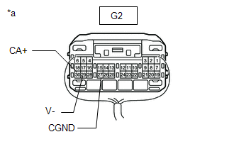
(b) Measure the voltage according to the value(s) in the table below.
Standard Voltage:
|
Tester Connection |
Switch Condition |
Specified Condition |
|---|---|---|
|
G2-30 (CA+) - Body ground |
Ignition switch ON |
5.5 to 7.05 V |
| NG |
|
|
|
5. |
CHECK REAR TELEVISION CAMERA ASSEMBLY |
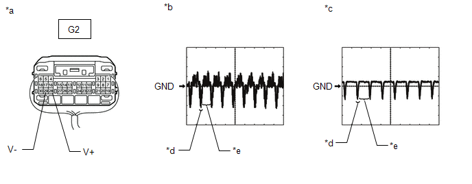
(a) Check the waveform of the rear television camera assembly using an oscilloscope.

|
*a |
Component with harness connected (Radio and Display Receiver Assembly) |
*b |
Waveform 1 |
|
*c |
Waveform 2 |
*d |
Synchronized Signal |
|
*e |
Video Waveform |
- |
- |
HINT:
A waterproof connector is used for the rear television camera assembly. Therefore, inspect the waveform at the radio and display receiver assembly with the connector connected.
OK:
Waveform is as shown in the illustration.
|
Item |
Content |
|---|---|
|
Terminal No. (Symbol) |
G2-28 (V+) - G2-29 (V-) |
|
Tool Setting |
200 mV/DIV., 50 μsec./DIV. |
|
Condition |
Waveform 1: Ignition switch ON, camera lens is not covered, displaying an image Waveform 2: Ignition switch ON, camera lens is covered, blacking out the screen |
HINT:
The video waveform changes according to the image sent by the rear television camera assembly.
| OK |
|
|
|
6. |
REPLACE REAR TELEVISION CAMERA ASSEMBLY |
(a) Replace the rear television camera assembly with a new or normally functioning one.
Click here
|
|
7. |
CHECK FOR DTC |
(a) Clear the DTCs.
Click here
Body Electrical > Navigation System > Clear DTCs
(b) Check for DTCs.
Click here
Body Electrical > Navigation System > Trouble Codes
OK:
No DTCs are output.
| OK |
|
END (REAR TELEVISION CAMERA ASSEMBLY WAS DEFECTIVE) |
| NG |
|
|
8. |
CHECK DTC (PANORAMIC VIEW MONITOR SYSTEM) |
(a) Clear the DTCs.
for Gasoline Model: Click here
for HV Model: Click here
Chassis > Circumference Monitoring Camera Control Module > Clear DTCs
(b) Recheck for DTCs and check that no DTCs are output.
for Gasoline Model: Click here
for HV Model: Click here
Chassis > Circumference Monitoring Camera Control Module > Trouble Codes
OK:
No DTCs are output.
| NG |
|
GO TO PANORAMIC VIEW MONITOR SYSTEM for HV model: Click here
for Gasoline model: Click here
|
|
|
9. |
CHECK HARNESS AND CONNECTOR (PARKING ASSIST ECU - RADIO AND DISPLAY RECEIVER ASSEMBLY) |
(a) Disconnect the N24 parking assist ECU connector.
(b) Disconnect the G2 radio and display receiver assembly connector.
(c) Measure the resistance according to the value(s) in the table below.
Standard Resistance:
|
Tester Connection |
Condition |
Specified Condition |
|---|---|---|
|
N24-7 (NS+) - G2-28 (V+) |
Always |
Below 1 Ω |
|
N24-24 (NS-) - G2-29 (V-) |
Always |
Below 1 Ω |
|
N24-7 (NS+) - Body ground |
Always |
10 kΩ or higher |
|
N24-24 (NS-) - Body ground |
Always |
10 kΩ or higher |
|
N24-8 (NSG) - Body ground |
Always |
10 kΩ or higher |
| NG |
|
REPAIR OR REPLACE HARNESS OR CONNECTOR |
|
|
10. |
CHECK PARKING ASSIST ECU |
|
*a |
Component with harness connected (Radio and Display Receiver Assembly) |
*b |
Waveform 1 |
|
*c |
Waveform 2 |
*d |
Synchronized Signal |
|
*e |
Video Waveform |
- |
- |
(a) Remove the radio and display receiver assembly with the connector still connected.
Click here
(b) Check the waveform of the parking assist ECU using an oscilloscope.
|
Item |
Content |
|
Measurement terminal |
G2-28 (V+) - G2-29 (V-) |
|
Measurement setting |
200 mV/DIV., 50 μsec./DIV. |
|
Condition |
Waveform 1: Ignition switch ON, shift position in R, camera lens is not covered, displaying an image. Waveform 2: Ignition switch ON, shift position in R, camera lens is covered, blacking out the screen. |
HINT:
- The video waveform changes according to the image sent by the parking assist ECU.
- The video waveform is constantly output when the ignition switch is ACC.
OK:
Waveform is similar to that shown in the illustration.
| OK |
|
| NG |
|
GO TO PANORAMIC VIEW MONITOR SYSTEM for Gasoline Model: Click here
for HV Model: Click here
|
|
|
|