- Shift Position
- Shift Position Sensor (PNB)
- Shift Position Sensor (PR)
- Shift Position Sensor (DB1)
- Shift Position Sensor (DB2)
- Shift Position Sensor (N)
- Shift Position Sensor (R)
- Shift Position Sensor (P)
| Last Modified: 01-30-2024 | 6.11:8.1.0 | Doc ID: RM100000001EKLQ |
| Model Year Start: 2019 | Model: RAV4 HV | Prod Date Range: [11/2018 - 08/2020] |
| Title: HYBRID / BATTERY CONTROL: HYBRID CONTROL SYSTEM (for 2WD with NICKEL METAL HYDRIDE BATTERY): P070562; Transmission Range Sensor "A" Circuit (PRNDL Input) Signal Compare Failure; 2019 - 2020 MY RAV4 HV [11/2018 - 08/2020] | ||
|
DTC |
P070562 |
Transmission Range Sensor "A" Circuit (PRNDL Input) Signal Compare Failure |
DESCRIPTION
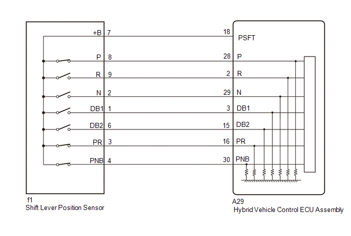
The shift lever position sensor sends 7 different switch signals to the hybrid vehicle control ECU assembly. The hybrid vehicle control ECU assembly uses these signals to detect the shift lever position (P, R, N or D). The hybrid vehicle control ECU assembly also uses this information to determine the intended direction of travel (forward or reverse).
|
DTC No. |
Detection Item |
DTC Detection Condition |
Trouble Area |
MIL |
Warning Indicate |
|---|---|---|---|---|---|
|
P070562 |
Transmission Range Sensor "A" Circuit (PRNDL Input) Signal Compare Failure |
Shift sensor circuit malfunction (abnormal pattern) A malfunction in the P, R, N or D circuit is detected based on the shift sensor input pattern. (1 trip detection logic) |
|
Does not come on |
Master Warning: Comes on |
Related Data List
|
DTC No. |
Data List |
|---|---|
|
P070562 |
|
CONFIRMATION DRIVING PATTERN
HINT:
After repair has been completed, clear the DTCs and then check that the vehicle has returned to normal by performing the following All Readiness check procedure.
Click here
![2019 - 2020 MY RAV4 HV [11/2018 - 08/2020]; HYBRID / BATTERY CONTROL: HYBRID CONTROL SYSTEM (for 2WD with NICKEL METAL HYDRIDE BATTERY): UTILITY](/t3Portal/stylegraphics/info.gif)
- Connect the Techstream to the DLC3.
- Turn the power switch on (IG) and turn the Techstream on.
- Clear the DTCs (even if no DTCs are stored, perform the clear DTC procedure).
- Turn the power switch off and wait for 2 minutes or more.
- Turn the power switch on (IG) and turn the Techstream on.
- Slowly move the shift lever from P to S then back to P.
- Enter the following menus: Powertrain / Hybrid Control / Utility / All Readiness.
-
Check the DTC judgment result.
HINT:
- If the judgment result shows NORMAL, the system is normal.
- If the judgment result shows ABNORMAL, the system has a malfunction.
- If the judgment result shows INCOMPLETE, perform driving pattern again.
WIRING DIAGRAM
PROCEDURE
|
1. |
READ VALUE USING TECHSTREAM (SHIFT POSITION SENSOR) |
(a) Connect the Techstream to the DLC3.
(b) Turn the power switch on (IG).
(c) Enter the following menus: Powertrain / Hybrid Control / Data List / Shift Position Sensor (PNB), Shift Position Sensor (PR), Shift Position Sensor (DB1), Shift Position Sensor (DB2), Shift Position Sensor (N), Shift Position Sensor (R) and Shift Position Sensor (P).
(d) While slowly moving the shift lever from P to S, then back to P, read the Data List (Shift Position Sensor) displayed on the Techstream.
Powertrain > Hybrid Control > Data List
|
Tester Display |
|---|
|
Shift Position Sensor (PNB) |
|
Shift Position Sensor (PR) |
|
Shift Position Sensor (DB1) |
|
Shift Position Sensor (DB2) |
|
Shift Position Sensor (N) |
|
Shift Position Sensor (R) |
|
Shift Position Sensor (P) |
HINT:
Be sure to move the shift lever slowly.
Standard:
|
Data List |
Shift Position |
|||
|
P |
R |
N |
D or S |
|
|
Shift Position Sensor (P) |
ON |
OFF |
OFF |
OFF |
|
Shift Position Sensor (R) |
OFF |
ON |
OFF |
OFF |
|
Shift Position Sensor (PR) |
ON |
ON |
OFF |
OFF |
|
Shift Position Sensor (N) |
OFF |
OFF |
ON |
OFF |
|
Shift Position Sensor (DB1) |
OFF |
OFF |
OFF |
ON |
|
Shift Position Sensor (DB2) |
OFF |
OFF |
OFF |
ON |
|
Shift Position Sensor (PNB) |
ON |
OFF |
ON |
OFF |
(e) Check for DTCs.
Powertrain > Hybrid Control > Trouble Codes
OK:
DTC P070562 is not output.
(f) Turn the power switch off.
| NG |

|
|

|
2. |
CHECK FOR INTERMITTENT PROBLEMS |
Click here
| OK |
|
REPLACE HYBRID VEHICLE CONTROL ECU ASSEMBLY
|
| NG |
|
REPAIR OR REPLACE MALFUNCTIONING PARTS, COMPONENT AND AREA |
|
3. |
INSPECT SHIFT LEVER POSITION SENSOR |
(a) Turn the power switch on (IG).
(b) Measure the voltage according to the value(s) in the table below.
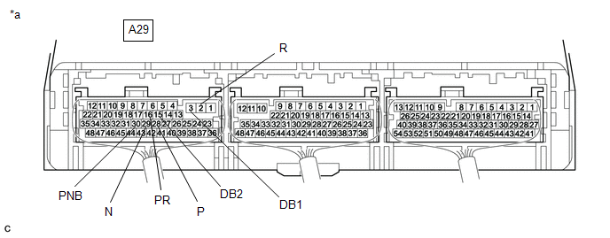
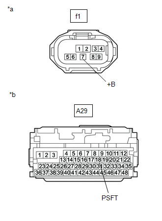
|
*a |
Component with harness connected (Hybrid Vehicle Control ECU Assembly) |
- |
- |
Standard Voltage:
|
Tester Connection |
Condition |
Specified Condition |
|---|---|---|
|
A29-28 (P) - Body ground |
Power switch on (IG) Shift lever in P |
7.5 to 14 V |
|
Power switch on (IG) Shift lever in any position except P |
0 to 1.5 V |
|
|
A29-2 (R) - Body ground |
Power switch on (IG) Shift lever in R |
7.5 to 14 V |
|
Power switch on (IG) Shift lever in any position except R |
0 to 1.5 V |
|
|
A29-29 (N) - Body ground |
Power switch on (IG) Shift lever in N |
7.5 to 14 V |
|
Power switch on (IG) Shift lever in any position except N |
0 to 1.5 V |
|
|
A29-3 (DB1) - Body ground |
Power switch on (IG) Shift lever in D or S |
7.5 to 14 V |
|
Power switch on (IG) Shift lever in any position except D or S |
0 to 1.5 V |
|
|
A29-15 (DB2) - Body ground |
Power switch on (IG) Shift lever in D or S |
7.5 to 14 V |
|
Power switch on (IG) Shift lever in any position except D or S |
0 to 1.5 V |
|
|
A29-16 (PR) - Body ground |
Power switch on (IG) Shift lever in P or R |
7.5 to 14 V |
|
Power switch on (IG) Shift lever in any position except P or R |
0 to 1.5 V |
|
|
A29-30 (PNB) - Body ground |
Power switch on (IG) Shift lever in P or N |
7.5 to 14 V |
|
Power switch on (IG) Shift lever in any position except P or N |
0 to 1.5 V |
(c) Turn the power switch off.
| OK |
|
REPLACE HYBRID VEHICLE CONTROL ECU ASSEMBLY
|
|
|
4. |
CHECK HARNESS AND CONNECTOR (POWER SOURCE CIRCUIT) |
|
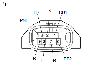
(a) Disconnect the f1 shift lever position sensor connector. |
|
(b) Turn the power switch on (IG).
|
(c) Measure the voltage according to the value(s) in the table below. Standard Voltage:
NOTICE: Turning the power switch on (IG) with the shift lever position sensor connector disconnected causes other DTCs to be stored. Clear the DTCs after performing this inspection. |
|

(d) Turn the power switch off.
(e) Reconnect the f1 shift lever position sensor connector.
| NG |
|
|
|
5. |
INSPECT SHIFT LEVER POSITION SENSOR |
|
(a) Disconnect the f1 shift lever position sensor connector. |
|
|
(b) Measure the resistance according to the value(s) in the table below. Standard Resistance:
HINT: Terminal No. 5 on the component side connector is empty. |
|
(c) Reconnect the f1 shift lever position sensor connector.
| OK |
|
REPAIR OR REPLACE HARNESS OR CONNECTOR |
| NG |
|
|
6. |
CHECK HARNESS AND CONNECTOR (SHIFT LEVER POSITION SENSOR - HYBRID VEHICLE CONTROL ECU ASSEMBLY) |
(a) Disconnect the f1 shift lever position sensor connector.
(b) Disconnect the A29 hybrid vehicle control ECU assembly connector.
|
(c) Measure the resistance according to the value(s) in the table below. Standard Resistance:
|
|
(d) Reconnect the A29 hybrid vehicle control ECU assembly connector.
(e) Reconnect the f1 shift lever position sensor connector.
| OK |
|
REPLACE HYBRID VEHICLE CONTROL ECU ASSEMBLY
|
| NG |
|
REPAIR OR REPLACE HARNESS OR CONNECTOR |
|
|
|