| Last Modified: 01-30-2024 | 6.11:8.1.0 | Doc ID: RM100000001EH0F |
| Model Year Start: 2019 | Model: RAV4 | Prod Date Range: [11/2018 - 10/2019] |
| Title: CELLULAR COMMUNICATION: TOYOTA ENTUNE SYSTEM: DCM Data Signal Circuit between Navigation ECU and DCM; 2019 MY RAV4 RAV4 HV [11/2018 - 10/2019] | ||
|
DCM Data Signal Circuit between Navigation ECU and DCM |
DESCRIPTION
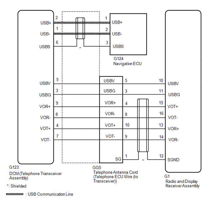
This circuit is used to send and receive signals between the DCM (Telephone Transceiver Assembly) and radio and display receiver assembly.
WIRING DIAGRAM
PROCEDURE
|
1. |
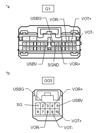
CHECK HARNESS AND CONNECTOR (RADIO AND DISPLAY RECEIVER ASSEMBLY - TELEPHONE ANTENNA CORD (TELEPHONE ECU WIRE (TO TRANSCEIVER))) |
(a) Disconnect the G1 radio and display receiver assembly connector.
(b) Disconnect the GG5 telephone antenna cord (telephone ECU wire (to Transceiver)) connector.
|
(c) Measure the resistance according to the value(s) in the table below. Standard Resistance:
|
|
| NG |

|
REPAIR OR REPLACE HARNESS OR CONNECTOR |
|

|
2. |
CHECK TELEPHONE ANTENNA CORD (TELEPHONE ECU WIRE (TO TRANSCEIVER)) |
|
(a) Disconnect the G123 telephone antenna cord (telephone ECU wire (to Transceiver)) connector from the DCM (telephone transceiver assembly). |
|
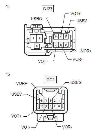
(b) Disconnect the GG5 telephone antenna cord (telephone ECU wire (to Transceiver)) connector from the wire harness.
(c) Measure the resistance according to the value(s) in the table below.
Standard Resistance:
|
Tester Connection |
Condition |
Specified Condition |
|---|---|---|
|
G123-5 (USBV) - GG5-5 (USBV) |
Always |
Below 1 Ω |
|
G123-3 (USBG) - GG5-3 (USBG) |
Always |
Below 1 Ω |
|
G123-9 (VOR+) - GG5-4 (VOR+) |
Always |
Below 1 Ω |
|
G123-8 (VOR-) - GG5-8 (VOR-) |
Always |
Below 1 Ω |
|
G123-4 (VOT+) - GG5-10 (VOT+) |
Always |
Below 1 Ω |
|
G123-7 (VOT-) - GG5-9 (VOT-) |
Always |
Below 1 Ω |
|
G123-5 (USBV) - Body ground |
Always |
10 kΩ or higher |
|
G123-3 (USBG) - Body ground |
Always |
10 kΩ or higher |
|
G123-9 (VOR+) - Body ground |
Always |
10 kΩ or higher |
|
G123-8 (VOR-) - Body ground |
Always |
10 kΩ or higher |
|
G123-4 (VOT+) - Body ground |
Always |
10 kΩ or higher |
|
G123-7 (VOT-) - Body ground |
Always |
10 kΩ or higher |
| NG |
|
REPLACE TELEPHONE ANTENNA CORD (TELEPHONE ECU WIRE (TO TRANSCEIVER)) |
|
|
3. |
CHECK TELEPHONE ANTENNA CORD (TELEPHONE ECU WIRE (TO TRANSCEIVER)) |
|
(a) Disconnect the G123 telephone antenna cord (telephone ECU wire (to transceiver)) connector from the DCM (telephone transceiver assembly). |
|
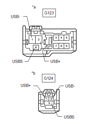
(b) Disconnect the G124 telephone antenna cord (telephone ECU wire (to transceiver)) connector from the navigation ECU.
(c) Measure the resistance according to the value(s) in the table below.
Standard Resistance:
|
Tester Connection |
Condition |
Specified Condition |
|---|---|---|
|
G123-2 (USB+) - G124-1 (USB+) |
Always |
Below 1 Ω |
|
G123-1 (USB-) - G124-2 (USB-) |
Always |
Below 1 Ω |
|
G123-6 (USBS) - G124-3 (USBS) |
Always |
Below 1 Ω |
|
G123-2 (USB+) - Body ground |
Always |
10 kΩ or higher |
|
G123-1 (USB-) - Body ground |
Always |
10 kΩ or higher |
|
G123-6 (USBS) - Body ground |
Always |
10 kΩ or higher |
| OK |
|
PROCEED TO NEXT SUSPECTED AREA SHOWN IN PROBLEM SYMPTOMS TABLE
|
![2019 MY RAV4 RAV4 HV [11/2018 - 02/2019]; CELLULAR COMMUNICATION: TOYOTA ENTUNE SYSTEM: PROBLEM SYMPTOMS TABLE](/t3Portal/stylegraphics/info.gif)
| NG |
|
REPLACE TELEPHONE ANTENNA CORD (TELEPHONE ECU WIRE (TO TRANSCEIVER)) |
|
|
|