| Last Modified: 01-30-2024 | 6.11:8.1.0 | Doc ID: RM100000001EH0A |
| Model Year Start: 2019 | Model: RAV4 | Prod Date Range: [11/2018 - 10/2019] |
| Title: CELLULAR COMMUNICATION: SAFETY CONNECT SYSTEM: B1571; Manual (SOS) Switch Green Indicator Malfunction; 2019 MY RAV4 RAV4 HV [11/2018 - 10/2019] | ||
|
DTC |
B1571 |
Manual (SOS) Switch Green Indicator Malfunction |
DESCRIPTION
This DTC is set when the DCM (Telephone Transceiver Assembly) detects an open or short in the manual (SOS) switch green indicator circuit of the manual (SOS) switch. The manual (SOS) switch green indicator illuminates after the ignition switch is turned to ON.
If the safety connect system is not active, the manual (SOS) switch green indicator will turn off.
If the safety connect system is active, the manual (SOS) switch green indicator will blink while communicating with the call center.
|
DTC No. |
Detection Item |
DTC Detection Condition |
Trouble Area |
|---|---|---|---|
|
B1571 |
Manual (SOS) Switch Green Indicator Malfunction |
Current for manual (SOS) switch green indicator reaches malfunction criteria for 10 seconds when ignition switch is ON. |
|
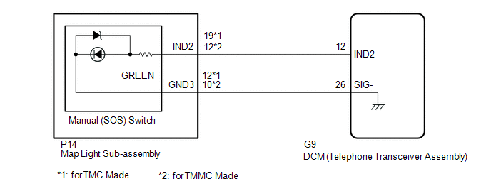
WIRING DIAGRAM
CAUTION / NOTICE / HINT
HINT:
Before performing this diagnostic procedure, make sure to perform Health Check and confirm that the DCM/VIN registration information is correct.
Click here
![2019 MY RAV4 RAV4 HV [11/2018 - 10/2019]; CELLULAR COMMUNICATION: SAFETY CONNECT SYSTEM: HEALTH CHECK](/t3Portal/stylegraphics/info.gif)
PROCEDURE
|
1. |
CHECK DTC |
(a) Turn the ignition switch off.
(b) Connect the Techstream to the DLC3.
(c) Turn the ignition switch to ON and wait for 10 seconds.
(d) Turn the Techstream on.
(e) Clear the DTCs.
Click here
Body Electrical > Telematics > Clear DTCs
(f) Recheck for DTCs.
Click here
Body Electrical > Telematics > Trouble Codes
|
Result |
Proceed to |
|---|---|
|
DTC B1570, B1571 and B15C5 are output |
A |
|
DTC B1571 is output (DTC B1570 and B15C5 are not output) |
B |
| B |

|
|

|
2. |
INSPECT MAP LIGHT SUB-ASSEMBLY (GREEN INDICATOR) |
|
(a) Remove the map light sub-assembly. Click here
|
|
(b) Connect 2 dry-cell batteries (1.5 V each) in series.
(c) for TMC Made:
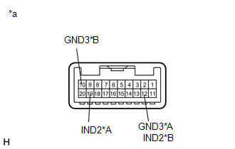
Connect the positive (+) lead to terminal 19 (IND2) and the negative (-) lead to terminal 12 (GND3) of the map light sub-assembly connector.
for TMMC Made:
Connect the positive (+) lead to terminal 12 (IND2) and the negative (-) lead to terminal 10 (GND3) of the map light sub-assembly connector.
(d) Check if the illumination for the manual (SOS) switch green indicator comes on.
OK:
Green indicator comes on.
| NG |
|
|
|
3. |
CHECK HARNESS AND CONNECTOR (DCM (TELEPHONE TRANSCEIVER ASSEMBLY) - MAP LIGHT SUB-ASSEMBLY) |
(a) Disconnect the G9 DCM (Telephone Transceiver Assembly) connector.
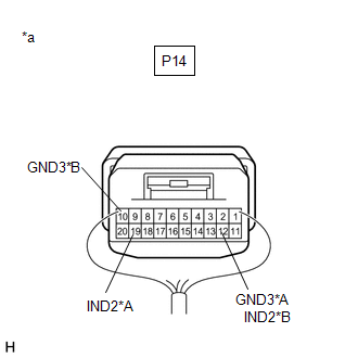
(b) Disconnect the P14 map light sub-assembly connector.
(c) Measure the resistance according to the value(s) in the table below.
Standard Resistance:
for TMC Made:
|
Tester Connection |
Condition |
Specified Condition |
|---|---|---|
|
G9-26 (SIG-) - P14-12 (GND3) |
Always |
Below 1 Ω |
|
G9-26 (SIG-) or P14-12 (GND3) - Body ground |
Always |
10 kΩ or higher |
|
G9-12 (IND2) - P14-19 (IND2) |
Always |
Below 1 Ω |
|
G9-12 (IND2) or P14-19 (IND2) - Body ground |
Always |
10 kΩ or higher |
for TMMC Made:
|
Tester Connection |
Condition |
Specified Condition |
|---|---|---|
|
G9-26 (SIG-) - P14-10 (GND3) |
Always |
Below 1 Ω |
|
G9-26 (SIG-) or P14-10 (GND3) - Body ground |
Always |
10 kΩ or higher |
|
G9-12 (IND2) - P14-12 (IND2) |
Always |
Below 1 Ω |
|
G9-12 (IND2) or P14-12 (IND2) - Body ground |
Always |
10 kΩ or higher |
| NG |
|
REPAIR OR REPLACE HARNESS OR CONNECTOR |
|
|
4. |
REPLACE DCM (TELEPHONE TRANSCEIVER ASSEMBLY) |
(a) Replace the DCM (Telephone Transceiver Assembly).
Click here
NOTICE:
- The ignition switch must be off.
- Do not exchange the DCM (Telephone Transceiver Assembly) with one from another vehicle.
| NEXT |
|
|
5. |
CHECK MAP LIGHT SUB-ASSEMBLY (MANUAL (SOS) SWITCH GREEN INDICATOR CONDITION) |
(a) Confirm the green indicator status after the ignition switch is turned to ON.
Click here
|
Result |
Proceed to |
|---|---|
|
Green indicator remains off |
A |
|
Green indicator remains on |
B |
| B |
|
|
|
6. |
CHECK MAP LIGHT SUB-ASSEMBLY (GREEN INDICATOR INPUT VOLTAGE) |
|
(a) Remove the map light sub-assembly but do not disconnect the connectors. Click here
|
|
(b) for TMC Made:
Connect the positive lead of a voltmeter to terminal P14-19 (IND2), and the negative lead to terminal P14-12 (GND3).
for TMMC Made:
Connect the positive lead of a voltmeter to terminal P14-12 (IND2), and the negative lead to terminal P14-10 (GND3).
(c) Measure the voltage.
Standard:
1.0 to 8.5 V for 2 seconds after the ignition switch is turned to ON and red indicator has turned off.
0 V when the ignition switch is off.
| OK |
|
|
|
7. |
CHECK DCM (TELEPHONE TRANSCEIVER ASSEMBLY) (GREEN INDICATOR OUTPUT VOLTAGE) |
|
(a) Remove the DCM (Telephone Transceiver Assembly) but do not disconnect the connectors. Click here
|
|
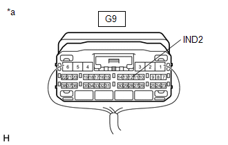
(b) Connect the positive lead of a voltmeter to terminal G9-12 (IND2), and the negative lead to body ground.
(c) Measure the voltage.
Standard:
1.0 to 8.5 V for 2 seconds after the ignition switch is turned to ON and red indicator has turned off.
0 V when the ignition switch is off.
| OK |
|
REPAIR OR REPLACE HARNESS OR CONNECTOR |
|
|
8. |
CHECK HARNESS AND CONNECTOR (DCM (TELEPHONE TRANSCEIVER ASSEMBLY) - BODY GROUND) |
|
(a) Remove the DCM (Telephone Transceiver Assembly) but do not disconnect the connectors. Click here
|
|
(b) Measure the resistance according to the value(s) in the table below.
Standard Resistance:
|
Tester Connection |
Condition |
Specified Condition |
|---|---|---|
|
G9-12 (IND2) - Body ground |
Always |
10 kΩ or higher |
| NG |
|
REPAIR OR REPLACE HARNESS OR CONNECTOR |
|
|
9. |
REPLACE DCM (TELEPHONE TRANSCEIVER ASSEMBLY) |
(a) Replace the DCM (Telephone Transceiver Assembly).
Click here
NOTICE:
- The ignition switch must be off.
- Do not exchange the DCM (Telephone Transceiver Assembly) with one from another vehicle.
| NEXT |
|
|
10. |
REPLACE DCM (TELEPHONE TRANSCEIVER ASSEMBLY) |
(a) Replace the DCM (Telephone Transceiver Assembly).
Click here
NOTICE:
- The ignition switch must be off.
- Do not exchange the DCM (Telephone Transceiver Assembly) with one from another vehicle.
| NEXT |
|
|
|
|