| Last Modified: 01-30-2024 | 6.11:8.1.0 | Doc ID: RM100000001EF3U |
| Model Year Start: 2019 | Model: RAV4 | Prod Date Range: [11/2018 - ] |
| Title: MIRROR (EXT): OUTER REAR VIEW MIRROR GLASS: INSPECTION; 2019 - 2024 MY RAV4 RAV4 HV [11/2018 - ] | ||
INSPECTION
PROCEDURE
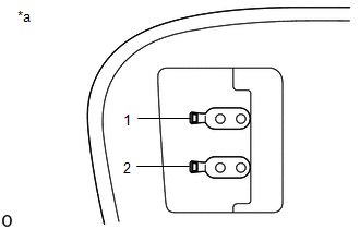
1. INSPECT OUTER MIRROR LH (w/o Blind Spot Monitor System)
|
(a) Check the outer mirror heater operation. (1) Measure the resistance according to the value(s) in the table below. Standard Resistance:
If the result is not as specified, replace the outer mirror LH. |
|
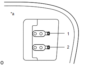
2. INSPECT OUTER MIRROR RH (w/o Blind Spot Monitor System)
|
(a) Check the outer mirror heater operation. (1) Measure the resistance according to the value(s) in the table below. Standard Resistance:
If the result is not as specified, replace the outer mirror RH. |
|
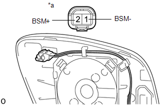
3. INSPECT OUTER MIRROR LH (w/ Blind Spot Monitor System)
|
(a) Check the outer mirror heater operation. (1) Measure the resistance according to the value(s) in the table below. Standard Resistance:
If the result is not as specified, replace the outer mirror LH. |
|
(b) Check the outer rear view mirror indicator operation.
(1) Connect 4 new 1.5 V dry-cell batteries in series.
|
(2) Apply 6 V dry-cell batteries to the terminals of the connector, and check the blind spot monitor indicator condition. NOTICE:
OK:
If the result is not as specified, replace the outer mirror LH. |
|
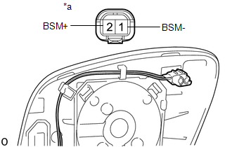
4. INSPECT OUTER MIRROR RH (w/ Blind Spot Monitor System)
|
(a) Check the outer mirror heater operation. (1) Measure the resistance according to the value(s) in the table below. Standard Resistance:
If the result is not as specified, replace the outer mirror RH. |
|
(b) Check the outer rear view mirror indicator operation.
(1) Connect 4 new 1.5 V dry-cell batteries in series.
|
(2) Apply 6 V dry-cell batteries to the terminals of the connector, and check the blind spot monitor indicator condition. NOTICE:
OK:
If the result is not as specified, replace the outer mirror RH. |
|
|
|
|