| Last Modified: 01-30-2024 | 6.11:8.1.0 | Doc ID: RM100000001EAC0 |
| Model Year Start: 2019 | Model: RAV4 | Prod Date Range: [11/2018 - 02/2019] |
| Title: BRAKE CONTROL / DYNAMIC CONTROL SYSTEMS: ELECTRONICALLY CONTROLLED BRAKE SYSTEM (w/o Vacuum Brake Booster): C1247,C1346,C1392; Stroke Sensor; 2019 MY RAV4 RAV4 HV [11/2018 - 02/2019] | ||
|
DTC |
C1247 |
Stroke Sensor |
|
DTC |
C1346 |
Abnormal Learning of Stroke Sensor Zero Point (Test Mode DTC) |
|
DTC |
C1392 |
Zero Point Calibration of Stroke Sensor undone |
DESCRIPTION
The brake pedal stroke sensor assembly sends a signal about the pedal stroke to the skid control ECU (brake booster with master cylinder assembly).
DTC C1346 will be cleared when the brake pedal stroke sensor assembly sends a brake pedal stroke sensor assembly signal or when Test Mode ends. DTC C1346 is output only in Test Mode.
|
DTC No. |
Detection Item |
INF Code |
DTC Detection Condition |
Trouble Area |
Note |
|---|---|---|---|---|---|
|
C1247 |
Stroke Sensor |
211 212 213 214 215 216 217 218 219 220 221 222 223 |
|
|
- |
|
C1346 |
Abnormal Learning of Stroke Sensor Zero Point (Test Mode DTC) |
- |
Detected only during Test Mode. |
|
- |
|
C1392 |
Zero Point Calibration of Stroke Sensor undone |
- |
Zero point calibration of brake pedal stroke sensor assembly is unfinished. |
|
- |
DTC Detection Conditions: C1247 INF Code: 214
|
Vehicle Condition |
|||
|---|---|---|---|
|
Pattern 1 |
Pattern 2 |
||
|
Diagnosis Condition |
- |
- |
- |
|
Malfunction Status |
Fluctuation of sensor output 1 (SKS1) is out of specification |
○ |
- |
|
The difference between the present value and last value of the sensor output voltage 1(SKS1) is 8.5% or more (0.43 V or more) of the sensor supply voltage (VCM1) |
- |
○ |
|
|
Detection Time |
- |
0.2 seconds or more |
|
|
Number of Trips |
1 trip |
1 trip |
|
HINT:
DTC will be output when conditions for either of the patterns in the table above are met.
DTC Detection Conditions: C1247 INF Code: 215
|
Vehicle Condition |
|||
|---|---|---|---|
|
Pattern 1 |
Pattern 2 |
||
|
Diagnosis Condition |
- |
- |
- |
|
Malfunction Status |
Fluctuation of sensor output 2 (SKS2) is out of specification |
○ |
- |
|
The difference between the present value and last value of the sensor output voltage 2(SKS2) is 8.5% or more (0.43 V or more) of the sensor supply voltage (VCM1) |
- |
○ |
|
|
Detection Time |
- |
0.2 seconds or more |
|
|
Number of Trips |
1 trip |
1 trip |
|
HINT:
DTC will be output when conditions for either of the patterns in the table above are met.
DTC Detection Conditions: C1247 INF Code: 216
|
Vehicle Condition |
|||
|---|---|---|---|
|
Pattern 1 |
Pattern 2 |
||
|
Diagnosis Condition |
- |
- |
- |
|
Malfunction Status |
Pedal off position (zero point stored value) is out of specification |
○ |
- |
|
The zero point stored value for the sensor output voltage 1 (SKS1) is deviates -17% to 25.9% (0.15 to 2.3 V) or more from the theoretical value |
- |
○ |
|
|
Detection Time |
- |
- |
|
|
Number of Trips |
1 trip |
1 trip |
|
HINT:
DTC will be output when conditions for either of the patterns in the table above are met.
DTC Detection Conditions: C1247 INF Code: 217
|
Vehicle Condition |
|||
|---|---|---|---|
|
Pattern 1 |
Pattern 2 |
||
|
Diagnosis Condition |
- |
- |
- |
|
Malfunction Status |
Pedal off position (zero point stored value) is out of specification |
○ |
- |
|
The zero point stored value for the sensor output voltage 2 (SKS2) deviates -31.7% to 17% (2.42 to 4.85 V) or more from the theoretical value |
- |
○ |
|
|
Detection Time |
- |
- |
|
|
Number of Trips |
1 trip |
1 trip |
|
HINT:
DTC will be output when conditions for either of the patterns in the table above are met.
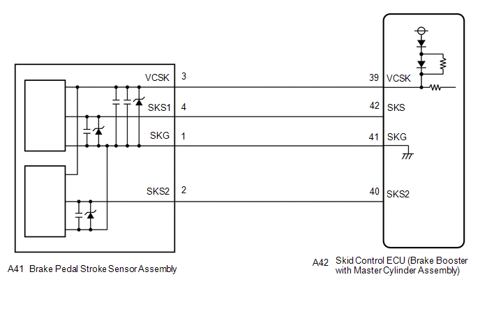
WIRING DIAGRAM
CAUTION / NOTICE / HINT
NOTICE:
When replacing the skid control ECU (brake booster with master cylinder assembly) or brake pedal stroke sensor assembly, perform initialization and calibration of the linear solenoid valve.
Click here
![2019 MY RAV4 RAV4 HV [11/2018 - 02/2019]; BRAKE CONTROL / DYNAMIC CONTROL SYSTEMS: ELECTRONICALLY CONTROLLED BRAKE SYSTEM (w/o Vacuum Brake Booster): UTILITY](/t3Portal/stylegraphics/info.gif)
HINT:
Check the condition of each related circuit connector before troubleshooting.
Click here
PROCEDURE
|
1. |
CHECK BRAKE PEDAL |
(a) Check that the brake pedal and the brake pedal stroke sensor assembly are properly installed and that the pedal can be depressed normally.
(b) Check and adjust the brake pedal height.
Click here
(c) Adjust the brake pedal stroke sensor assembly.
Click here
|

|
2. |
CHECK HARNESS AND CONNECTOR (BRAKE BOOSTER WITH MASTER CYLINDER ASSEMBLY - BRAKE PEDAL STROKE SENSOR ASSEMBLY) |
(a) Make sure that there is no looseness at the locking part and the connecting part of the connectors.
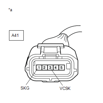
(b) Disconnect the A42 skid control ECU (brake booster with master cylinder assembly) connector.
(c) Disconnect the A41 brake pedal stroke sensor assembly connector.
(d) Check both the connector case and the terminal for deformation and corrosion.
OK:
No deformation or corrosion.
(e) Measure the resistance according to the value(s) in the table below.
Standard Resistance:
|
Tester Connection |
Condition |
Specified Condition |
|---|---|---|
|
A42-39 (VCSK) - A41-3 (VCSK) |
Always |
Below 1 Ω |
|
A42-39 (VCSK) or A41-3 (VCSK) - Body ground |
Always |
10 kΩ or higher |
|
A42-41 (SKG) - A41-1 (SKG) |
Always |
Below 1 Ω |
|
A42-41 (SKG) or A41-1 (SKG) - Body ground |
Always |
10 kΩ or higher |
|
A42-42 (SKS) - A41-4 (SKS1) |
Always |
Below 1 Ω |
|
A42-42 (SKS) or A41-4 (SKS1) - Body ground |
Always |
10 kΩ or higher |
|
A42-40 (SKS2) - A41-2 (SKS2) |
Always |
Below 1 Ω |
|
A42-40 (SKS2) or A41-2 (SKS2) - Body ground |
Always |
10 kΩ or higher |
| NG |

|
REPAIR OR REPLACE HARNESS OR CONNECTOR |
|
|
3. |
INSPECT BRAKE BOOSTER WITH MASTER CYLINDER ASSEMBLY (SENSOR OUTPUT) |
|
(a) Reconnect the A42 skid control ECU (brake booster with master cylinder assembly) connector. |
|
(b) Turn the power switch on (IG).
(c) Measure the voltage according to the value(s) in the table below.
Standard Voltage:
|
Tester Connection |
Switch Condition |
Specified Condition |
|---|---|---|
|
A41-3 (VCSK) - A41-1 (SKG) |
Power switch on (IG) |
4.84 to 5.16 V |
| OK |
|
| NG |
|
|
|
|