| Last Modified: 01-30-2024 | 6.11:8.1.0 | Doc ID: RM100000001E4Z8 |
| Model Year Start: 2019 | Model: RAV4 | Prod Date Range: [11/2018 - 10/2019] |
| Title: AUDIO / VIDEO: AUDIO AND VISUAL SYSTEM: Sound Signal Circuit between Radio Receiver and Stereo Jack Adapter; 2019 MY RAV4 RAV4 HV [11/2018 - 10/2019] | ||
|
Sound Signal Circuit between Radio Receiver and Stereo Jack Adapter |
DESCRIPTION
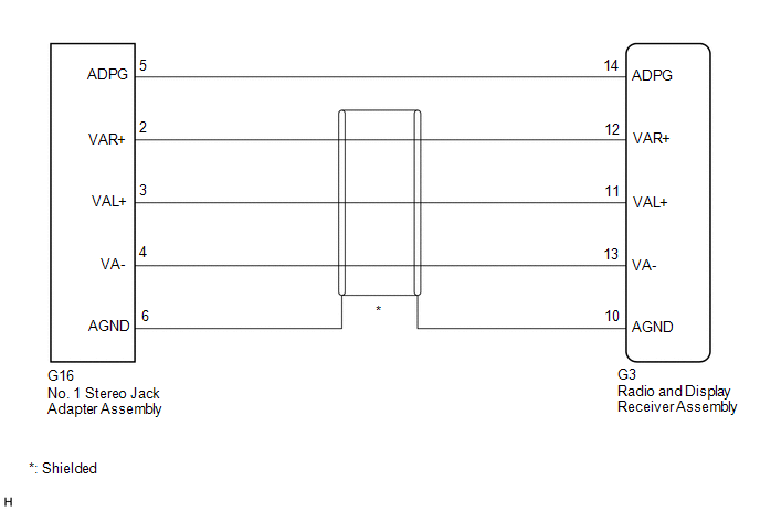
The No. 1 stereo jack adapter assembly sends the sound signal from an external device to the radio and display receiver assembly via this circuit.
The sound signal that has been sent is amplified by the radio and display receiver assembly and then is sent to the speakers.
If there is an open or short in the circuit, sound cannot be heard from the speakers even if there is no malfunction in the radio and display receiver assembly or speakers.
WIRING DIAGRAM
PROCEDURE
|
1. |
CHECK HARNESS AND CONNECTOR (RADIO AND DISPLAY RECEIVER ASSEMBLY - NO. 1 STEREO JACK ADAPTER ASSEMBLY) |
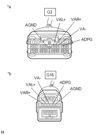
(a) Disconnect the G3 radio and display receiver assembly connector.
(b) Disconnect the G16 No. 1 stereo jack adapter assembly connector.
|
(c) Measure the resistance according to the value(s) in the table below. Standard Resistance:
|
|
| OK |

|
PROCEED TO NEXT SUSPECTED AREA SHOWN IN PROBLEM SYMPTOMS TABLE |
| NG |
|
REPAIR OR REPLACE HARNESS OR CONNECTOR |
|
|
|