| Last Modified: 01-30-2024 | 6.11:8.1.0 | Doc ID: RM100000001E4YK |
| Model Year Start: 2019 | Model: RAV4 | Prod Date Range: [11/2018 - 10/2022] |
| Title: AUDIO / VIDEO: AUDIO AND VISUAL SYSTEM: Radio Broadcast cannot be Received or Poor Reception; 2019 - 2022 MY RAV4 RAV4 HV [11/2018 - 10/2022] | ||
|
Radio Broadcast cannot be Received or Poor Reception |
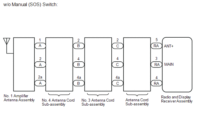
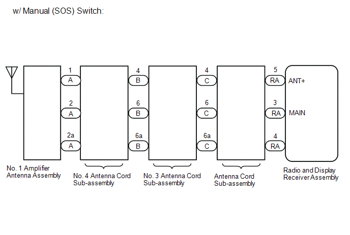
WIRING DIAGRAM
CAUTION / NOTICE / HINT
NOTICE:
When replacing the radio and display receiver assembly, always replace it with a new one. If a radio and display receiver assembly which was installed to another vehicle is used, the following may occur:
- A communication malfunction DTC may be stored.
- The radio and display receiver assembly may not operate normally.
HINT:
Depending on the parts that are replaced during vehicle inspection or maintenance, performing initialization, registration or calibration may be needed. Refer to Precaution for Audio and Visual System.
Click here
![2019 MY RAV4 RAV4 HV [11/2018 - 10/2019]; AUDIO / VIDEO: AUDIO AND VISUAL SYSTEM: PRECAUTION](/t3Portal/stylegraphics/info.gif)
PROCEDURE
|
1. |
CHECK RADIO AND DISPLAY RECEIVER ASSEMBLY |
(a) Check the radio automatic station search function by activating it.
OK:
Automatic station search function stops on a station.
| OK |

|
|

|
2. |
CHECK OPTIONAL COMPONENTS |
(a) Check if any optional components that may decrease reception capacity, such as sunshade film or a telephone antenna, are installed.
OK:
Optional components are not installed.
NOTICE:
Do not remove optional components without the permission of the customer.
| NG |
|
REMOVE OPTIONAL COMPONENTS AND CHECK AGAIN (SEE NOTICE ABOVE) |
|
|
3. |
CHECK RADIO AND DISPLAY RECEIVER ASSEMBLY |
|
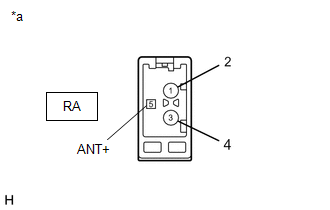
(a) Preparation for check (1) Disconnect the RA radio and display receiver assembly connector. |
|
(b) Check for noise
(1) Turn the ignition switch to ON with the radio and display receiver assembly connector connected.
(2) Turn the radio and display receiver assembly on and tune into AM mode.
(3) Place a screwdriver, thin wire or other metal object on the radio and display receiver assembly antenna jack and check that noise can be heard from the speakers.
OK:
Noise can be heard from the speakers.
| NG |
|
|
|
4. |
INSPECT RADIO AND DISPLAY RECEIVER ASSEMBLY |
(a) Disconnect the RA radio and display receiver assembly connector.
|
(b) Measure the voltage according to the value(s) in the table below. Standard Voltage:
|
|
| NG |
|
|
|
5. |
CHECK VEHICLE CONDITION |
(a) Check the vehicle condition.
|
Result |
Proceed to |
|---|---|
|
w/o Manual (SOS) Switch |
A |
|
w/ Manual (SOS) Switch |
B |
| B |
|
|
|
6. |
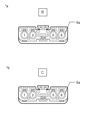
CHECK NO. 4 ANTENNA CORD SUB-ASSEMBLY |
|
(a) Disconnect the antenna connector from the No. 1 amplifier antenna assembly. |
|
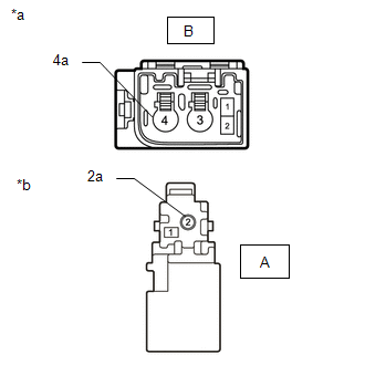
(b) Disconnect the antenna connector from the No. 3 antenna cord sub-assembly.
(c) Measure the resistance according to the value(s) in the table below.
Standard Resistance:
|
Tester Connection |
Condition |
Specified Condition |
|---|---|---|
|
A-2 - B-4 |
Always |
Below 1 Ω |
|
A-2a - B-4a |
Always |
Below 1 Ω |
|
A-1 - B-2 |
Always |
Below 1 Ω |
|
A-2 - Body ground |
Always |
10 kΩ or higher |
|
A-1 - Body ground |
Always |
10 kΩ or higher |
| NG |
|
|
|
7. |
CHECK NO. 3 ANTENNA CORD SUB-ASSEMBLY |
|
(a) Disconnect the antenna connector from the No. 4 antenna cord sub-assembly. |
|
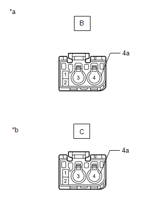
(b) Disconnect the antenna connector from the antenna cord sub-assembly.
(c) Measure the resistance according to the value(s) in the table below.
Standard Resistance:
|
Tester Connection |
Condition |
Specified Condition |
|---|---|---|
|
B-4 - C-4 |
Always |
Below 1 Ω |
|
B-4a - C-4a |
Always |
Below 1 Ω |
|
B-2 - C-2 |
Always |
Below 1 Ω |
|
B-4 - Body ground |
Always |
10 kΩ or higher |
|
B-2 - Body ground |
Always |
10 kΩ or higher |
| NG |
|
|
|
8. |
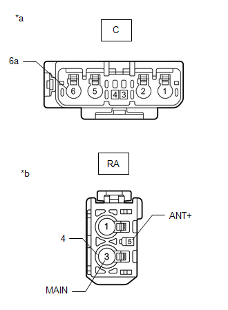
CHECK ANTENNA CORD SUB-ASSEMBLY |
|
(a) Disconnect the antenna connector from the No. 3 antenna cord sub-assembly. |
|
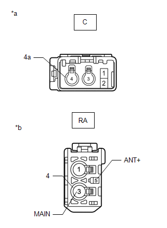
(b) Disconnect the antenna connector from the radio and display receiver assembly.
(c) Measure the resistance according to the value(s) in the table below.
Standard Resistance:
|
Tester Connection |
Condition |
Specified Condition |
|---|---|---|
|
C-4 - RA-3 (MAIN) |
Always |
Below 1 Ω |
|
C-4a - RA-4 |
Always |
Below 1 Ω |
|
C-2 - RA-5 (ANT+) |
Always |
Below 1 Ω |
|
C-4 - Body ground |
Always |
10 kΩ or higher |
|
C-2 - Body ground |
Always |
10 kΩ or higher |
| NG |
|
REPLACE ANTENNA CORD SUB-ASSEMBLY
|
|
|
9. |
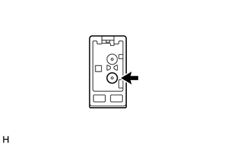
CHECK NO. 1 AMPLIFIER ANTENNA ASSEMBLY |
(a) Replace the No. 1 amplifier antenna assembly with a new or known good one.
Click here
OK:
Radio broadcasts can be received normally.
| OK |
|
END (NO. 1 AMPLIFIER ANTENNA ASSEMBLY IS DEFECTIVE) |
| NG |
|
|
10. |
CHECK NO. 4 ANTENNA CORD SUB-ASSEMBLY |
|
(a) Disconnect the antenna connector from the No. 1 amplifier antenna assembly. |
|
(b) Disconnect the antenna connector from the No. 3 antenna cord sub-assembly.
(c) Measure the resistance according to the value(s) in the table below.
Standard Resistance:
|
Tester Connection |
Condition |
Specified Condition |
|---|---|---|
|
A-2 - B-6 |
Always |
Below 1 Ω |
|
A-2a - B-6a |
Always |
Below 1 Ω |
|
A-1 - B-4 |
Always |
Below 1 Ω |
|
A-2 - Body ground |
Always |
10 kΩ or higher |
|
A-1 - Body ground |
Always |
10 kΩ or higher |
| NG |
|
|
|
11. |
CHECK NO. 3 ANTENNA CORD SUB-ASSEMBLY |
|
(a) Disconnect the antenna connector from the No. 4 antenna cord sub-assembly. |
|
(b) Disconnect the antenna connector from the antenna cord sub-assembly.
(c) Measure the resistance according to the value(s) in the table below.
Standard Resistance:
|
Tester Connection |
Condition |
Specified Condition |
|---|---|---|
|
B-6 - C-6 |
Always |
Below 1 Ω |
|
B-6a - C-6a |
Always |
Below 1 Ω |
|
B-4 - C-4 |
Always |
Below 1 Ω |
|
B-6 - Body ground |
Always |
10 kΩ or higher |
|
B-4 - Body ground |
Always |
10 kΩ or higher |
| NG |
|
|
|
12. |
CHECK ANTENNA CORD SUB-ASSEMBLY |
|
(a) Disconnect the antenna connector from the No. 3 antenna cord sub-assembly. |
|
(b) Disconnect the antenna connector from the radio and display receiver assembly.
(c) Measure the resistance according to the value(s) in the table below.
Standard Resistance:
|
Tester Connection |
Condition |
Specified Condition |
|---|---|---|
|
C-6 - RA-3 (MAIN) |
Always |
Below 1 Ω |
|
C-6a - RA-4 |
Always |
Below 1 Ω |
|
C-4 - RA-5 (ANT+) |
Always |
Below 1 Ω |
|
C-6 - Body ground |
Always |
10 kΩ or higher |
|
C-4 - Body ground |
Always |
10 kΩ or higher |
| OK |
|
| NG |
|
REPLACE ANTENNA CORD SUB-ASSEMBLY
|
|
|
|