| Last Modified: 01-30-2024 | 6.11:8.1.0 | Doc ID: RM100000001E4YA |
| Model Year Start: 2019 | Model: RAV4 | Prod Date Range: [11/2018 - 10/2019] |
| Title: AUDIO / VIDEO: AUDIO AND VISUAL SYSTEM: B15DB; Telematics Transceiver Disconnected; 2019 MY RAV4 RAV4 HV [11/2018 - 10/2019] | ||
|
DTC |
B15DB |
Telematics Transceiver Disconnected |
DESCRIPTION
If the radio and display receiver assembly cannot detect the DCM (telematics transceiver) for a certain period of time (90 seconds) after the ignition switch is turned to ACC and the radio and display receiver assembly confirms that the information is missing by checking past DCM (telematics transceiver) recognition information (registered information), this DTC will be stored.
The telematics system uses USB communication between devices. If an open, short, short to +B or short to ground occurs in the USB circuit, communication is interrupted and the telematics system will not operate normally.
|
DTC No. |
Detection Item |
DTC Detection Condition |
Trouble Area |
|---|---|---|---|
|
B15DB |
Telematics Transceiver Disconnected |
DCM (telematics transceiver) disconnected |
|
HINT:
This DTC may be stored due to environmental reasons such as electrical noise or interference.
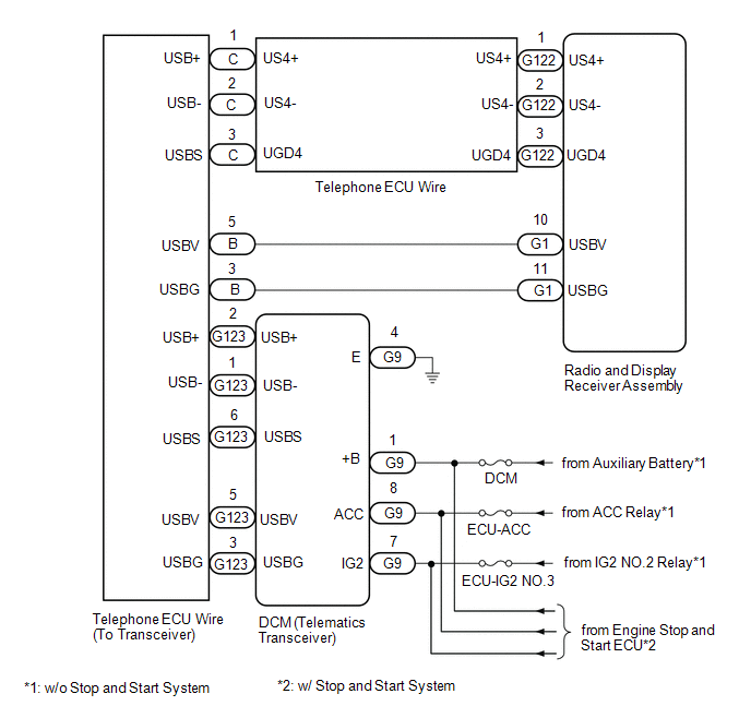
WIRING DIAGRAM
CAUTION / NOTICE / HINT
NOTICE:
-
When replacing the radio and display receiver assembly, always replace it with a new one. If a radio and display receiver assembly which was installed to another vehicle is used, the following may occur:
- A communication malfunction DTC may be stored.
- The radio and display receiver assembly may not operate normally.
- Inspect the fuses for circuits related to this system before performing the following procedure.
- When replacing the DCM (telematics transceiver), make sure to replace it with a new one.
-
Before replacing the DCM (telematics transceiver), refer to Registration.
for HV Model: Click here
![2019 MY RAV4 HV [11/2018 - 10/2019]; THEFT DETERRENT / KEYLESS ENTRY: SMART KEY SYSTEM (for Start Function, HV Model): REGISTRATION](/t3Portal/stylegraphics/info.gif)
for Gasoline Model: Click here
HINT:
Depending on the parts that are replaced during vehicle inspection or maintenance, performing initialization, registration or calibration may be needed. Refer to Precaution for Audio and Visual System.
Click here
PROCEDURE
|
1. |
CHECK DTC |
(a) Clear the DTCs.
Click here
Body Electrical > Navigation System > Clear DTCs
(b) Turn the ignition switch off.
(c) Turn the ignition switch to ON and wait for 90 seconds.
(d) Recheck for DTCs and check that no DTCs are output.
Click here
Body Electrical > Navigation System > Trouble Codes
OK:
No DTCs are output.
| OK |

|
|

|
2. |
CHECK HARNESS AND CONNECTOR (DCM [TELEMATICS TRANSCEIVER] POWER SOURCE) |
|
(a) Disconnect the DCM (telematics transceiver) connector. |
|
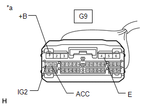
(b) Measure the resistance according to the value(s) in the table below.
Standard Resistance:
|
Tester Connection |
Condition |
Specified Condition |
|---|---|---|
|
G9-4 (E) - Body ground |
Always |
Below 1 Ω |
(c) Measure the voltage according to the value(s) in the table below.
Standard Voltage:
|
Tester Connection |
Switch Condition |
Specified Condition |
|---|---|---|
|
*1: w/ Stop and Start System
*2: w/o Stop and Start System |
||
|
G9-1 (+B) - G9-4 (E) |
Ignition switch off |
10.5 to 16 V*1 11 to 14 V*2 |
|
G9-8 (ACC) - G9-4 (E) |
Ignition switch ACC |
10.5 to 16 V*1 11 to 14 V*2 |
|
G9-7 (IG2) - G9-4 (E) |
Ignition switch ACC |
10.5 to 16 V*1 11 to 14 V*2 |
| NG |
|
REPAIR OR REPLACE HARNESS OR CONNECTOR |
|
|
3. |
INSPECT RADIO AND DISPLAY RECEIVER ASSEMBLY |
|
(a) Disconnect the radio and display receiver assembly connector. |
|
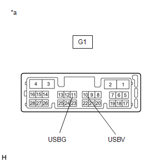
(b) Measure the resistance according to the value(s) in the table below.
Standard Resistance:
|
Tester Connection |
Condition |
Specified Condition |
|---|---|---|
|
G1-11 (USBG) - Body ground |
Always |
Below 1 Ω |
(c) Measure the voltage according to the value(s) in the table below.
Standard Voltage:
|
Tester Connection |
Switch Condition |
Specified Condition |
|---|---|---|
|
G1-10 (USBV) - G1-11 (USBG) |
Ignition switch ON |
4.75 to 5.25 V |
| NG |
|
|
|
4. |
INSPECT TELEPHONE ECU WIRE |
|
(a) Disconnect the radio and display receiver assembly connector. |
|
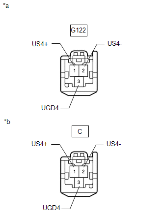
(b) Disconnect the telephone ECU wire connector from telephone ECU wire (to transceiver).
(c) Measure the resistance according to the value(s) in the table below.
Standard Resistance:
|
Tester Connection |
Condition |
Specified Condition |
|---|---|---|
|
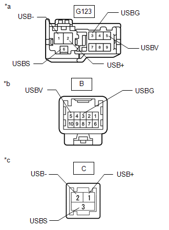
G122-1 (US4+) - C-1 (US4+) |
Always |
Below 1 Ω |
|
G122-2 (US4-) - C-2 (US4-) |
Always |
Below 1 Ω |
|
G122-3 (UGD4-) - C-3 (UGD4) |
Always |
Below 1 Ω |
|
G122-1 (US4+) - Body ground |
Always |
10 kΩ or higher |
|
G122-2 (US4-) - Body ground |
Always |
10 kΩ or higher |
|
G122-3 (UGD4-) - Body ground |
Always |
10 kΩ or higher |
| NG |
|
REPLACE TELEPHONE ECU WIRE |
|
|
5. |
CHECK HARNESS AND CONNECTOR (RADIO AND DISPLAY RECEIVER ASSEMBLY - DCM [TELEMATICS TRANSCEIVER]) |
(a) Disconnect the G1 radio and display receiver assembly connector.
(b) Disconnect the B telephone ECU wire (to transceiver) connector.
(c) Measure the resistance according to the value(s) in the table below.
Standard Resistance:
|
Tester Connection |
Condition |
Specified Condition |
|---|---|---|
|
G1-10 (USBV) - B-5 (USBV) |
Always |
Below 1 Ω |
|
G1-11 (USBG) - B-3 (USBG) |
Always |
Below 1 Ω |
|
G1-10 (USBV) - Body ground |
Always |
10 kΩ or higher |
|
G1-11 (USBG) - Body ground |
Always |
10 kΩ or higher |
| NG |
|
REPAIR OR REPLACE HARNESS OR CONNECTOR |
|
|
6. |
INSPECT TELEPHONE ECU WIRE (TO TRANSCEIVER) |
|
(a) Disconnect the telephone ECU wire (to transceiver) connector |
|
(b) Measure the resistance according to the value(s) in the table below.
Standard Resistance:
|
Tester Connection |
Condition |
Specified Condition |
|---|---|---|
|
G123-1 (USB-) - C-2 (USB-) |
Always |
Below 1 Ω |
|
G123-2 (USB+) - C-1 (USB+) |
Always |
Below 1 Ω |
|
G123-6 (USBS) - C-3 (USBS) |
Always |
Below 1 Ω |
|
G123-3 (USBG) - B-3 (USBG) |
Always |
Below 1 Ω |
|
G123-5 (USBV) - B-5 (USBV) |
Always |
Below 1 Ω |
|
G123-1 (USB-) - Body ground |
Always |
10 kΩ or higher |
|
G123-2 (USB+) - Body ground |
Always |
10 kΩ or higher |
|
G123-6 (USBS) - Body ground |
Always |
10 kΩ or higher |
|
G123-3 (USBG) - Body ground |
Always |
10 kΩ or higher |
|
G123-5 (USBV) - Body ground |
Always |
10 kΩ or higher |
| NG |
|
REPAIR OR REPLACE TELEPHONE ECU WIRE (TO TRANSCEIVER) |
|
|
7. |
REPLACE DCM (TELEMATICS TRANSCEIVER) |
(a) Replace the DCM (telematics transceiver) with a new one.
Click here
(b) Clear the DTCs.
Click here
Body Electrical > Navigation System > Clear DTCs
(c) Turn the ignition switch off.
(d) Turn the ignition switch to ON and wait for 90 seconds.
(e) Recheck for DTCs and check that no DTCs are output.
Click here
Body Electrical > Navigation System > Trouble Codes
OK:
No DTCs are output.
| OK |
|
END (DCM [TELEMATICS TRANSCEIVER] IS DEFECTIVE) |
| NG |
|
|
|
|