| Last Modified: 01-30-2024 | 6.11:8.1.0 | Doc ID: RM100000001E4XS |
| Model Year Start: 2019 | Model: RAV4 | Prod Date Range: [11/2018 - 10/2022] |
| Title: AUDIO / VIDEO: AUDIO AND VISUAL SYSTEM: B1324; Lost Communication with Meter; 2019 - 2022 MY RAV4 RAV4 HV [11/2018 - 10/2022] | ||
|
DTC |
B1324 |
Lost Communication with Meter |
DESCRIPTION
These DTCs are stored when communication between the radio and display receiver assembly and combination meter assembly is not possible.
|
DTC No. |
Detection Item |
DTC Detection Condition |
Trouble Area |
|---|---|---|---|
|
B1324 |
Lost Communication with Meter |
CAN reception error |
|
HINT:
The radio and display receiver assembly is the master unit.
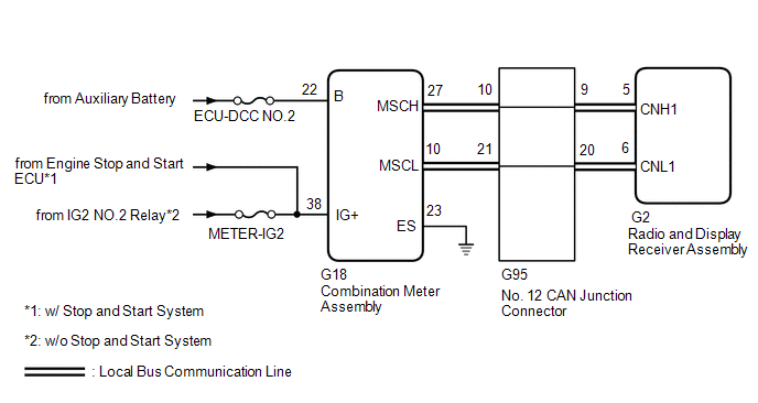
WIRING DIAGRAM
CAUTION / NOTICE / HINT
NOTICE:
-
When replacing the radio and display receiver assembly, always replace it with a new one. If a radio and display receiver assembly which was installed to another vehicle is used, the following may occur:
- A communication malfunction DTC may be stored.
- The radio and display receiver assembly may not operate normally.
- Inspect the fuses for circuits related to this system before performing the following procedure.
- When replacing the combination meter assembly, always replace it with a new one. If a combination meter assembly which was installed to another vehicle is used, the information stored in it will not match the information from the vehicle and a DTC may be stored.
HINT:
Depending on the parts that are replaced during vehicle inspection or maintenance, performing initialization, registration or calibration may be needed. Refer to Precaution for Audio and Visual System.
Click here
![2019 MY RAV4 RAV4 HV [11/2018 - 10/2019]; AUDIO / VIDEO: AUDIO AND VISUAL SYSTEM: PRECAUTION](/t3Portal/stylegraphics/info.gif)
PROCEDURE
|
1. |
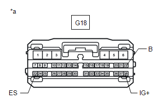
CHECK HARNESS AND CONNECTOR (COMBINATION METER ASSEMBLY POWER SOURCE) |
|
(a) Disconnect the combination meter assembly connector. |
|
(b) Measure the resistance according to the value(s) in the table below.
Standard Resistance:
|
Tester Connection |
Condition |
Specified Condition |
|---|---|---|
|
G18-23 (ES) - Body ground |
Always |
Below 1 Ω |
(c) Measure the voltage according to the value(s) in the table below.
Standard Voltage:
|
Tester Connection |
Switch Condition |
Specified Condition |
|---|---|---|
|
G18-22 (B) - Body ground |
Ignition switch off |
11 to 14 V |
|
G18-38 (IG+) - Body ground |
Ignition switch ON |
10.5 to 16 V*1 11 to 14 V*2 |
*1: w/ Stop and Start System
*2: w/o Stop and Start System
| NG |

|
REPAIR OR REPLACE HARNESS OR CONNECTOR |
|

|
2. |
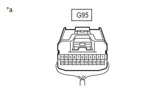
CHECK HARNESS AND CONNECTOR (COMBINATION METER ASSEMBLY - NO. 12 JUNCTION CONNECTOR) |
|
(a) Disconnect the cable from the negative (-) auxiliary battery terminal. |
|
(b) Disconnect the No. 12 junction connector.
(c) Measure the resistance according to the value(s) in the table below.
Standard Resistance:
|
Tester Connection |
Condition |
Specified Condition |
|---|---|---|
|
G95-10 - G95-21 |
Cable disconnected from negative (-) auxiliary battery terminal |
108 to 132 Ω |
| NG |
|
|
|
3. |
CHECK HARNESS AND CONNECTOR (RADIO AND DISPLAY RECEIVER ASSEMBLY - NO. 12 JUNCTION CONNECTOR) |
|
(a) Disconnect the cable from the negative (-) auxiliary battery terminal. |
|
(b) Disconnect the No. 12 junction connector.
(c) Measure the resistance according to the value(s) in the table below.
Standard Resistance:
|
Tester Connection |
Condition |
Specified Condition |
|---|---|---|
|
G95-9 - G95-20 |
Cable disconnected from negative (-) auxiliary battery terminal |
108 to 132 Ω |
| OK |
|
REPLACE NO. 12 JUNCTION CONNECTOR |
|
|
4. |
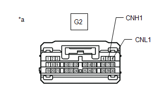
CHECK HARNESS AND CONNECTOR (RADIO AND DISPLAY RECEIVER ASSEMBLY - NO. 12 JUNCTION CONNECTOR) |
|
(a) Disconnect the cable from the negative (-) auxiliary battery terminal. |
|
(b) Disconnect the radio and display receiver assembly connector.
(c) Measure the resistance according to the value(s) in the table below.
Standard Resistance:
|
Tester Connection |
Condition |
Specified Condition |
|---|---|---|
|
G2-5 (CNH1) - G2-6 (CNL1) |
Cable disconnected from negative (-) auxiliary battery terminal |
108 to 132 Ω |
| OK |
|
| NG |
|
REPAIR OR REPLACE HARNESS OR CONNECTOR |
|
5. |
CHECK HARNESS AND CONNECTOR (COMBINATION METER ASSEMBLY - NO. 12 JUNCTION CONNECTOR) |
|
(a) Disconnect the cable from the negative (-) auxiliary battery terminal. |
|
(b) Disconnect the combination meter assembly connector.
(c) Measure the resistance according to the value(s) in the table below.
Standard Resistance:
|
Tester Connection |
Condition |
Specified Condition |
|---|---|---|
|
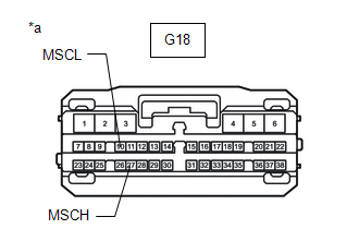
G18-27 (MSCH) - G18-10 (MSCL) |
Cable disconnected from negative (-) auxiliary battery terminal |
108 to 132 Ω |
| OK |
|
| NG |
|
REPAIR OR REPLACE HARNESS OR CONNECTOR |
|
|
|