- Perform "Reset Memory"
- Perform acceleration sensor zero point calibration and system information memorization
| Last Modified: 08-21-2023 | 6.11:8.1.0 | Doc ID: RM100000001YTZQ |
| Model Year Start: 2022 | Model: Avalon HV | Prod Date Range: [08/2021 - ] |
| Title: REAR SUSPENSION: REAR SHOCK ABSORBER: REMOVAL; 2022 MY Avalon Avalon HV [08/2021 - ] | ||
REMOVAL
CAUTION / NOTICE / HINT
The necessary procedures (adjustment, calibration, initialization, or registration) that must be performed after parts are removed and installed, or replaced during rear shock absorber assembly removal/installation are shown below.
Necessary Procedures After Parts Removed/Installed/Replaced (for Gasoline Model:)
|
Replaced Part or Performed Procedure |
Necessary Procedure |
Effect/Inoperative Function when Necessary Procedure not Performed |
Link |
|---|---|---|---|
|
Rear wheel alignment adjustment |
|
|
|
|
Suspension, tires, etc. (The vehicle height changes because of suspension or tire replacement.) |
|
|
|
|
Rear television camera assembly optical axis adjustment (Back camera position setting) |
Parking Assist Monitor System |
||
|
Panoramic View Monitor System |
Necessary Procedures After Parts Removed/Installed/Replaced (for HV Model:)
|
Replaced Part or Performed Procedure |
Necessary Procedure |
Effect/Inoperative Function when Necessary Procedure not Performed |
Link |
|---|---|---|---|
|
Rear wheel alignment adjustment |
|
|
|
|
Suspension, tires, etc. (The vehicle height changes because of suspension or tire replacement.) |
|
|
|
|
Rear television camera assembly optical axis adjustment (Back camera position setting) |
Parking Assist Monitor System |
||
|
Panoramic View Monitor System |
HINT:
- Use the same procedure for the RH side and LH side.
- The following procedure is for the LH side.
PROCEDURE
1. REMOVE REAR WHEEL
2. REMOVE NO. 2 FLOOR UNDER COVER (for Gasoline Model 2WD)
(a) for LH Side:
3. REMOVE NO. 1 FLOOR UNDER COVER (for Gasoline Model 2WD)
(a) for RH Side:
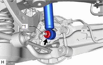
4. LOOSEN REAR SHOCK ABSORBER ASSEMBLY
|
(a) Loosen the nut of the rear shock absorber assembly. NOTICE: Hold the rear axle carrier pin while rotating the nut. |
|
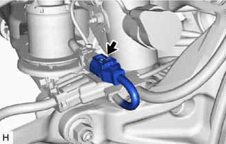
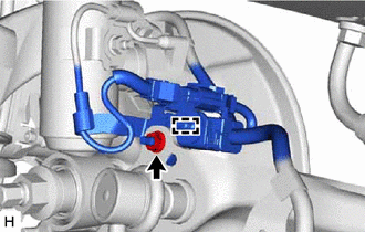
5. SEPARATE NO. 2 PARKING BRAKE WIRE ASSEMBLY (w/ AVS)
|
(a) Disconnect the connector. |
|
|
(b) Remove the nut. |
|
(c) Disengage the clamp and separate the No. 2 parking brake wire assembly.
6. REMOVE REAR STABILIZER LINK ASSEMBLY
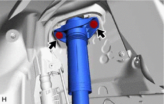
7. SEPARATE REAR SHOCK ABSORBER ASSEMBLY
|
(a) Remove the 2 bolts and separate the rear shock absorber assembly from the vehicle. |
|
8. SEPARATE REAR UPPER CONTROL ARM ASSEMBLY
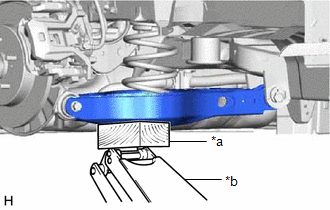
|
(a) Using a jack and wooden block, support the rear No. 2 suspension arm assembly. NOTICE:
|
|
|
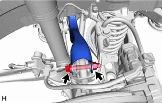
(b) Remove the bolt and nut, and separate the rear upper control arm assembly from the rear axle carrier sub-assembly. NOTICE: Because the nut has its own stopper, do not turn the nut. Loosen the bolt with the nut secured. |
|
9. REMOVE REAR SHOCK ABSORBER ASSEMBLY
|
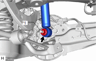
(a) Remove the nut, plate washer and rear shock absorber assembly from the rear axle carrier sub-assembly. NOTICE: Hold the rear axle carrier pin while rotating the nut. |
|
10. REMOVE REAR SHOCK ABSORBER CAP
|
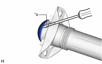
(a) Using a screwdriver with its tip wrapped with protective tape, remove the rear shock absorber cap from the rear shock absorber assembly. |
|
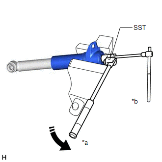
11. REMOVE REAR SUSPENSION SUPPORT ASSEMBLY
|
(a) Secure the rear shock absorber assembly in a vise using aluminum plates. NOTICE: Do not overtighten the vise. |
|
(b) Using SST and a 6 mm hexagon socket wrench, hold the rear shock absorber rod and remove the rear support to rear shock absorber nut.
SST: 09729-97202
(c) Remove the rear suspension support assembly from the rear shock absorber assembly.
|
|
|
![2022 MY Avalon [08/2021 - ]; BRAKE CONTROL / DYNAMIC CONTROL SYSTEMS: ELECTRONICALLY CONTROLLED BRAKE SYSTEM (for Gasoline Model): CALIBRATION](/t3Portal/stylegraphics/info.gif)
