- Wireless door lock control system
- Smart key system (for Entry Function)
- Smart key system (for Start Function)
- Steering lock function
| Last Modified: 08-21-2023 | 6.11:8.1.0 | Doc ID: RM100000001YPFL |
| Model Year Start: 2022 | Model: Avalon HV | Prod Date Range: [08/2021 - ] |
| Title: POWER DISTRIBUTION: MAIN BODY ECU: REMOVAL; 2022 MY Avalon Avalon HV [08/2021 - ] | ||
REMOVAL
CAUTION / NOTICE / HINT
The necessary procedures (adjustment, calibration, initialization, or registration) that must be performed after parts are removed and installed, or replaced during main body ECU (multiplex network body ECU) removal/installation are shown below.
Necessary Procedure After Parts Removed/Installed/Replaced (for Gasoline Model)
|
Replaced Part or Performed Procedure |
Necessary Procedure |
Effect/Inoperative Function when Necessary Procedure not Performed |
Link |
|---|---|---|---|
|
*: When performing learning using the Techstream.
Click here
|
|||
|
Disconnect cable from negative battery terminal |
Perform steering sensor zero point calibration |
Lane Tracing Assist System |
|
|
Pre-collision System |
|||
|
Intelligent clearance sonar system* |
|||
|
Lighting system (for Gasoline Model with Cornering Light) |
|||
|
Memorize steering angle neutral point |
Parking assist monitor system |
|
|
|
Panoramic view monitor system |
|
||
|
Main body ECU (multiplex network body ECU) |
Code registration (Smart key System (for Start Function) |
|
|
CAUTION:
Some of these service operations affect the SRS airbag system. Read the precautionary notices concerning the SRS airbag system before servicing.
Click here
![2021 - 2022 MY Avalon [08/2020 - ]; SUPPLEMENTAL RESTRAINT SYSTEMS: AIRBAG SYSTEM (for Gasoline Model): PRECAUTION](/t3Portal/stylegraphics/info.gif)
Necessary Procedure After Parts Removed/Installed/Replaced (for HV Model)
|
Replaced Part or Performed Procedure |
Necessary Procedure |
Effect/Inoperative Function When Necessary Procedures are not Performed |
Link |
|---|---|---|---|
|
*: When performing learning using the Techstream.
Click here
|
|||
|
Disconnect cable from negative auxiliary battery terminal |
Perform steering sensor zero point calibration |
Lane Tracing Assist System |
|
|
Pre-collision System |
|||
|
Intelligent clearance sonar system* |
|||
|
Lighting system (for HV Model with Cornering Light) |
|||
|
Memorize steering angle neutral point |
Parking assist monitor system |
|
|
|
Panoramic view monitor system |
|
||
|
Main body ECU (multiplex network body ECU) |
Code registration (Smart key System (for Start Function) |
|
|
CAUTION:
Some of these service operations affect the SRS airbag system. Read the precautionary notices concerning the SRS airbag system before servicing.
Click here
PROCEDURE
1. REMOVE LOWER NO. 1 INSTRUMENT PANEL AIRBAG ASSEMBLY
Click here
2. REMOVE NO. 3 INSTRUMENT PANEL TO COWL BRACE SUB-ASSEMBLY
Click here
3. REMOVE INSTRUMENT PANEL JUNCTION BLOCK ASSEMBLY WITH MAIN BODY ECU
|
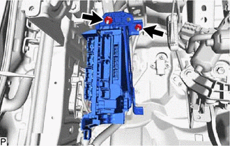
(a) Disconnect each connector. |
|
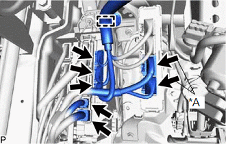
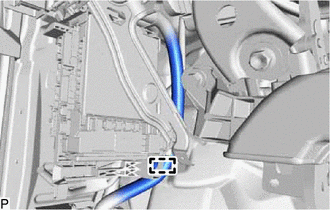
(b) Disengage the clamp.
(c) Disengage the 2 claws and pull down the 2 lock levers to disconnect the 2 connectors as shown in the illustration.

|
Remove in this Direction |
|
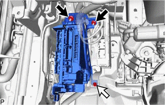
(d) Disconnect each connector. |
|
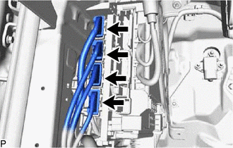
(e) for Gasoline Model:
|
(1) Remove the 2 nuts. |
|
(f) for HV Model:
(1) Remove the 2 nuts and bolt.

|
Nut |

|
Bolt |
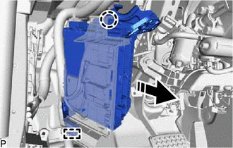
(g) Disengage the claw, guide and pull out the instrument panel junction block assembly with main body ECU.
|
|
Remove in this Direction |
|
(h) Disengage the clamp. |
|
|
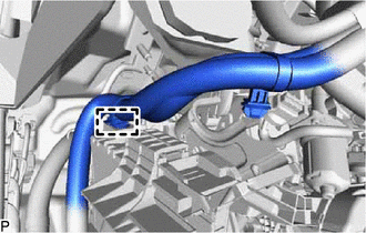
(i) Disengage the clamp. |
|
(j) Disengage the 2 claws and pull down the 2 lock levers to disconnect the 2 connectors as shown in the illustration and remove the instrument panel junction block assembly with main body ECU.
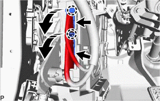
|
|
Remove in this Direction |
4. REMOVE WIRING HARNESS CLAMP BRACKET
|
(a) Remove the nut. |
|
(b) Disengage the guide to remove the wiring harness clamp bracket.
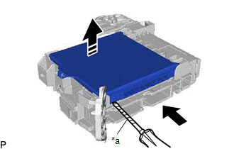
5. REMOVE MAIN BODY ECU (MULTIPLEX NETWORK BODY ECU)
(a) Press the claw of the instrument panel junction block assembly as shown in the illustration to release the lock.
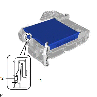
|
*1 |
Instrument Panel Junction Block Assembly |
|
*2 |
Main Body ECU (Multiplex Network Body ECU) |
|
|
Press in this Direction |
(b) With the instrument panel junction block assembly lock released, insert a screwdriver with its tip wrapped with protective tape horizontally between the main body ECU (multiplex network body ECU) and junction block assembly.
|
*a |
Protective Tape |
|
|
Insert in this Direction |
|
|
Remove in this Direction |
NOTICE:
- Use a screwdriver with a diameter between 5.0 mm (0.197 in.) and 6.3 mm (0.248 in.) and a length of approximately 90 mm (3.54 in.).
- Do not insert the screwdriver under the connector socket of the main body ECU (multiplex network body ECU).
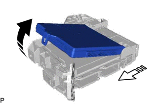
(c) Using the screwdriver, carefully raise the main body ECU (multiplex network body ECU) to the position where the connector becomes disconnected.
NOTICE:
Do not twist the screwdriver to raise the main body ECU (multiplex network body ECU).
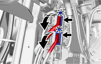
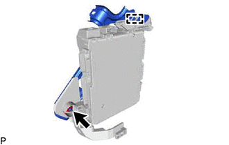
(d) Raise the main body ECU (multiplex network body ECU) as shown by the arrow (1), and then pull it out as shown by the arrow (2) in the illustration.
|
|
Remove in this Direction (1) |

|
Remove in this Direction (2) |
NOTICE:
Do not touch the main body ECU (multiplex network body ECU) connector.
|
|
|