- Replacement of No. 1 HV supply stack sub-assembly
- Replacement of No. 2 HV supply stack sub-assembly
| Last Modified: 09-10-2025 | 6.11:8.1.0 | Doc ID: RM100000001YOL2 |
| Model Year Start: 2022 | Model: Avalon HV | Prod Date Range: [08/2021 - ] |
| Title: HYBRID / BATTERY CONTROL: HV BATTERY STACK (for LITHIUM-ION BATTERY): REMOVAL; 2022 MY Avalon HV [08/2021 - ] | ||
REMOVAL
CAUTION / NOTICE / HINT
The necessary procedures (adjustment, calibration, initialization or registration) that must be performed after parts are removed and installed, or replaced during HV supply stack sub-assembly removal/installation are shown below.
Necessary Procedures After Parts Removed/Installed/Replaced
|
Replaced Part or Performed Procedure |
Necessary Procedure |
Effect/Inoperative Function when Necessary Procedure not Performed |
Link |
|---|---|---|---|
| *: When performing learning using the Techstream. | |||
|
Auxiliary battery terminal is disconnected/reconnected |
Perform steering sensor zero point calibration |
Lane Tracing Assist System |
|
|
Pre-collision system |
|||
|
Intelligent clearance sonar system* |
|||
|
Lighting System (for HV Model with Cornering Light) |
|||
|
Memorize steering angle neutral point |
Parking assist monitor system |
||
|
Panoramic view monitor system |
|||
|
|
|
HV battery status information cannot be updated |
|
|
Current sensor offset learning |
DTCs are stored |
|
|
Replacement of hybrid battery terminal block |
Perform high voltage fuse accumulated load history reset |
||
CAUTION:
-
Orange wire harnesses and connectors indicate high-voltage circuits. To prevent electric shock, always follow the procedure described in the repair manual.
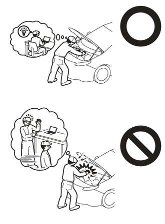
-
To prevent electric shock, wear insulated gloves when working on wire harnesses and components of the high voltage system.
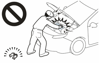
- The hybrid system has high-voltage circuits. Accidents, such as electric shock, or electric leaks may result if the hybrid system is not operated in a correct manner. Make sure to follow the correct procedure.
- When disposing of an HV battery or HV supply stack sub-assembly, make sure to return them through an authorized collection agent who is capable of handling them safely.
- Before returning an HV battery, make sure to perform a recovery inspection.
- Before returning an HV supply stack sub-assembly, make sure to perform a recovery inspection.
- Make a note of the output DTCs as some of them may be necessary for "Recovery Inspection" of the HV battery and HV supply stack sub-assemblies.
NOTICE:
- When replacing the No. 1 HV supply stack sub-assembly or No. 2 HV supply stack sub-assembly, it is necessary to check, adjust and equalize the SOC of the HV battery. Otherwise, the engine may run longer than normal, resulting in a decrease in fuel efficiency.
- After turning the power switch off, waiting time may be required before disconnecting the cable from the negative (-) auxiliary battery terminal. Therefore, make sure to read the disconnecting the cable from the negative (-) auxiliary battery terminal notices before proceeding with work.
PROCEDURE
PROCEDURE
1. READ VALUE USING TECHSTREAM
(a) Connect the Techstream to the DLC3.
(b) Turn the power switch on (IG).
(c) Enter the following menus: Powertrain / HV Battery / Data List / Hybrid Battery Temperature 1 to 6.
Powertrain > HV Battery > Data List
|
Tester Display |
|---|
|
Hybrid Battery Temperature 1 |
|
Hybrid Battery Temperature 2 |
|
Hybrid Battery Temperature 3 |
|
Hybrid Battery Temperature 4 |
|
Hybrid Battery Temperature 5 |
|
Hybrid Battery Temperature 6 |
(d) Read the Data List.
NOTICE:
If any of the temperatures listed in "Hybrid Battery Temperature 1 to 6" are 50°C or more, leave the vehicle until the temperature drops to less than 50°C.
2. REMOVE HV BATTERY
3. REMOVE UPPER HV BATTERY COVER SUB-ASSEMBLY
4. REMOVE NO. 1 HV BATTERY HOSE
5. REMOVE HV BATTERY JUNCTION BLOCK ASSEMBLY
6. REMOVE HYBRID BATTERY TERMINAL BLOCK
7. REMOVE NO. 2 HYBRID BATTERY SHIELD SUB-ASSEMBLY
CAUTION:
Be sure to wear insulated gloves and protective goggles.
|
(a) Remove the bolt, 3 nuts and No. 2 hybrid battery shield sub-assembly from the HV battery. |
|
8. REMOVE NO. 1 HV BATTERY INTAKE DUCT LH
CAUTION:
Be sure to wear insulated gloves and protective goggles.
|
(a) Remove the clip to disconnect the No. 1 hybrid battery intake duct LH from the HV battery. |
|
(b) Disengage the claw of the hybrid battery thermistor (sensor portion) and remove the No. 1 hybrid battery intake duct LH.
9. REMOVE BATTERY ECU ASSEMBLY
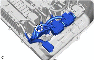
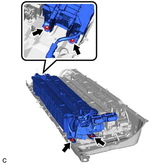
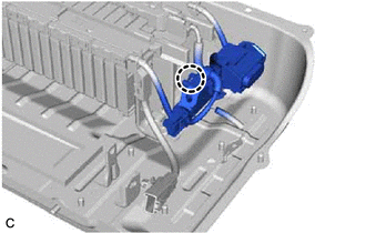
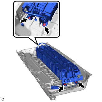
10. REMOVE NO. 1 HV SUPPLY STACK SUB-ASSEMBLY
CAUTION:
Be sure to wear insulated gloves and protective goggles.
|
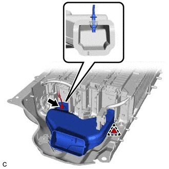
(a) Disconnect the connector. NOTICE: Insulate each disconnected high-voltage connector with insulating tape. Wrap the connector from the wire harness side to the end of the connector. |
|
|
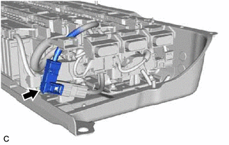
(b) Disconnect the connector. |
|
|
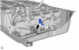
(c) Disengage the claw. |
|
|
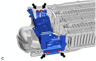
(d) Remove the 4 nuts and No. 1 HV supply stack sub-assembly. |
|
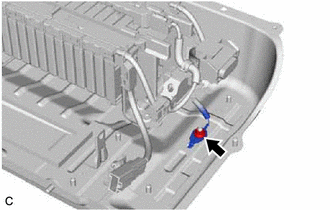
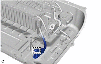
11. REMOVE NO. 2 HV SUPPLY STACK SUB-ASSEMBLY
CAUTION:
Be sure to wear insulated gloves and protective goggles.
|
(a) Remove the nut and disconnect the earth terminal. |
|
|
(b) Disengage the clamp. |
|
|
(c) Disengage the claw. |
|
|
(d) Remove the 4 nuts and No. 2 HV supply stack sub-assembly. |
|
12. PERFORM RECOVERY INSPECTION
(a) Before returning the HV supply stack sub-assembly, make sure to perform a recovery inspection.
|
|
|
![2019 - 2022 MY Avalon HV [04/2018 - ]; PARK ASSIST / MONITORING: INTELLIGENT CLEARANCE SONAR SYSTEM (for HV Model): CALIBRATION](/t3Portal/stylegraphics/info.gif)
