- DTCs are stored
- Slight vibration at a vehicle speed of 5 km/h (3 mph) or less
- Shock or vibration during acceleration
| Last Modified: 08-21-2023 | 6.11:8.1.0 | Doc ID: RM100000001YO5L |
| Model Year Start: 2022 | Model: Avalon HV | Prod Date Range: [08/2021 - ] |
| Title: A25A-FXS (FUEL): FUEL INJECTOR (for Port Injection): REMOVAL; 2022 MY Avalon HV [08/2021 - ] | ||
REMOVAL
CAUTION / NOTICE / HINT
The necessary procedures (adjustment, calibration, initialization or registration) that must be performed after parts are removed and installed, or replaced during port fuel injector assembly removal/installation are shown below.
Necessary Procedures After Parts Removed/Installed/Replaced
|
Replaced Part or Performed Procedure |
Necessary Procedure |
Effect/Inoperative Function when Necessary Procedure not Performed |
Link |
|---|---|---|---|
|
*: When performing learning using the Techstream.
Click here
|
|||
|
Auxiliary battery terminal is disconnected/reconnected |
Perform steering sensor zero point calibration |
Lane Tracing Assist System |
|
|
Pre-collision System |
|||
|
Intelligent Clearance Sonar System* |
|||
|
Lighting System (for HV Model with Cornering Light) |
|||
|
Memorize steering angle neutral point |
Parking Assist Monitor System |
|
|
|
Panoramic View Monitor System |
|
||
|
Replacement of inverter with converter assembly |
Resolver learning |
|
|
|
Replacement of ECM |
Perform Vehicle Identification Number (VIN) registration |
MIL illuminates |
|
|
Inspection after repair |
|
|
CAUTION:
-
Never perform work on fuel system components near any possible ignition sources.
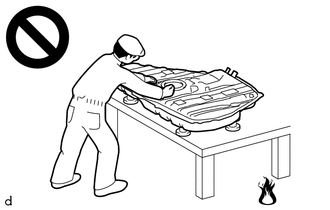
- Vaporized fuel could ignite, resulting in a serious accident.
-
Do not perform work on fuel system components without first disconnecting the cable from the negative (-) auxiliary battery terminal.
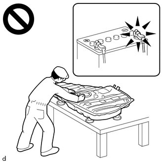
- Sparks could cause vaporized fuel to ignite, resulting in a serious accident.
-
To prevent serious injury due to fuel spray from the high-pressure fuel lines, always discharge fuel system pressure before removing any fuel system components.
NOTICE:
This procedure includes the removal of small-head bolts. Refer to Small-Head Bolts of Basic Repair Hint to identify the small-head bolts.
Click here
![2019 - 2022 MY Avalon Avalon HV [04/2018 - ]; INTRODUCTION: REPAIR INSTRUCTION: PRECAUTION](/t3Portal/stylegraphics/info.gif)
PROCEDURE
1. PRECAUTION
NOTICE:
After turning the power switch off, waiting time may be required before disconnecting the cable from the negative (-) auxiliary battery terminal. Therefore, make sure to read the disconnecting the cable from the negative (-) auxiliary battery terminal notices before proceeding with work.
Click here
2. DISCHARGE FUEL SYSTEM PRESSURE
Click here
3. REMOVE LUGGAGE TRIM SERVICE HOLE COVER
Click here
4. DISCONNECT CABLE FROM NEGATIVE AUXILIARY BATTERY TERMINAL
Click here
5. REMOVE THROTTLE BODY WITH MOTOR ASSEMBLY
Click here
6. REMOVE EGR VALVE ASSEMBLY
Click here
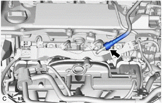
7. REMOVE NO. 2 WATER BY-PASS PIPE
Click here
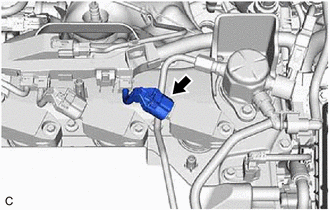
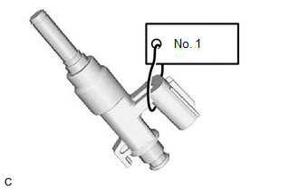
8. DISCONNECT FUEL TUBE SUB-ASSEMBLY
|
(a) Remove the fuel pipe clamp from the fuel tube connector. |
|
|
(b) Disconnect the fuel tube sub-assembly from the fuel delivery pipe sub-assembly. Click here
|
|
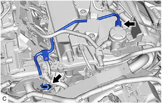
9. REMOVE NO. 1 FUEL PIPE SUB-ASSEMBLY
CAUTION:
To prevent serious injury due to fuel spray from the high-pressure fuel lines, always discharge fuel system pressure before removing any fuel system components.
|
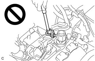
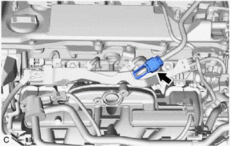
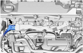
(a) Disconnect the ignition coil assembly connector. |
|
(b) for EGR Valve Bracket Connection Type:
|
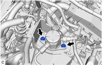
(1) Using a 17 mm union nut wrench, loosen the 2 union nuts of the No. 1 fuel pipe sub-assembly. |
|
(c) for Cylinder Head Cover Sub-assembly Connection Type:
(1) Using a 17 mm union nut wrench, loosen the 2 union nuts of the No. 1 fuel pipe sub-assembly.
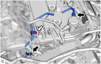

|
Union Nut |

|
Bolt |
(2) Using an 8 mm socket wrench, remove the bolt.
|
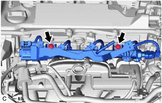
(d) Loosen the 2 bolts of the fuel pump assembly. |
|
(e) Remove the No. 1 fuel pipe sub-assembly from the fuel delivery pipe and fuel pump assembly.
10. REMOVE FUEL DELIVERY PIPE SUB-ASSEMBLY
|
(a) Disconnect the No. 5 engine wire connector. |
|
|
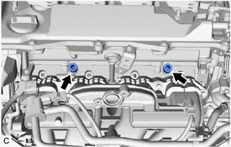
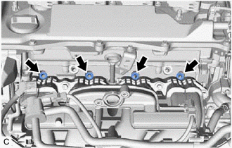
(b) Remove the 2 bolts and fuel delivery pipe sub-assembly with the 4 port fuel injector assemblies from the cylinder head sub-assembly. NOTICE: Be careful not to drop the port fuel injector assemblies when removing the fuel delivery pipe sub-assembly. |
|
11. REMOVE NO. 1 DELIVERY PIPE SPACER
|
(a) Remove the 2 No. 1 delivery pipe spacers from the cylinder head sub-assembly. |
|
12. REMOVE INJECTOR VIBRATION INSULATOR
|
(a) Remove the 4 injector vibration insulators from the cylinder head sub-assembly. |
|
13. REMOVE NO. 5 ENGINE WIRE
|
(a) Disconnect the 4 port fuel injector assembly connectors and fuel pressure sensor connector. |
|
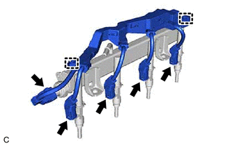
(b) Disengage the 2 clamps to remove the No. 5 engine wire from the fuel delivery pipe sub-assembly.
14. REMOVE PORT FUEL INJECTOR ASSEMBLY
|
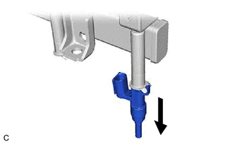
(a) Pull the 4 port fuel injector assemblies out of the fuel delivery pipe sub-assembly. |
|
|
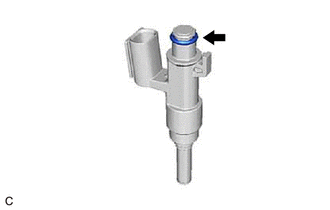
(b) Remove the O-ring from each port fuel injector assembly. |
|
|
(c) Attach a tag or label with the corresponding cylinder number to each port fuel injector assembly so that they can be installed to their original locations. NOTICE: Cover the port fuel injector assemblies with plastic bags to prevent damage and contamination. |
|
|
|
|