| Last Modified: 08-21-2023 | 6.11:8.1.0 | Doc ID: RM100000001YN7F |
| Model Year Start: 2022 | Model: Avalon HV | Prod Date Range: [08/2021 - ] |
| Title: BRAKE SYSTEM (OTHER): BRAKE BOOSTER PUMP(for HV Model): REMOVAL; 2022 MY Avalon HV [08/2021 - ] | ||
REMOVAL
CAUTION / NOTICE / HINT
The necessary procedures (adjustment, calibration, initialization, or registration) that must be performed after parts are removed, installed, or replaced during brake booster pump assembly removal/installation are shown below.
Necessary Procedures After Parts Removed/Installed/Replaced
|
Replaced Part or Performed Procedure |
Necessary Procedure |
Effect/Inoperative Function when Necessary Procedure not Performed |
Link |
|---|---|---|---|
|
*: When performing learning using the Techstream.
Click here
|
|||
|
Auxiliary battery terminal is disconnected/reconnected |
Perform steering sensor zero point calibration |
Lane Tracing Assist System |
|
|
Pre-collision System |
|||
|
Intelligent Clearance Sonar System* |
|||
|
Lighting System (for HV Model with Cornering Light) |
|||
|
Memorize steering angle neutral point |
Parking Assist Monitor System |
|
|
|
Panoramic View Monitor System |
|
||
NOTICE:
While the auxiliary battery is connected, even if the power switch is off, the brake control system activates when the brake pedal is depressed or any door courtesy switch turns on. Therefore, when servicing the brake system components, do not operate the brake pedal or open/close the doors while the auxiliary battery is connected.
PROCEDURE
1. PRECAUTION
NOTICE:
After turning the power switch off, waiting time may be required before disconnecting the cable from the negative (-) auxiliary battery terminal. Therefore, make sure to read the disconnecting the cable from the negative (-) auxiliary battery terminal notices before proceeding with work.
Click here
![2019 - 2022 MY Avalon Avalon HV [04/2018 - ]; INTRODUCTION: REPAIR INSTRUCTION: PRECAUTION](/t3Portal/stylegraphics/info.gif)
2. PERFORM ACCUMULATOR PRESSURE ZERO DOWN
Click here
3. REMOVE COWL TOP VENTILATOR LOUVER SUB-ASSEMBLY
Click here
4. REMOVE FRONT CENTER UPPER SUSPENSION BRACE SUB-ASSEMBLY
Click here
5. REMOVE NO. 1 ENGINE COVER SUB-ASSEMBLY
Click here
6. DRAIN BRAKE FLUID
NOTICE:
If brake fluid leaks onto any painted surface, immediately wash it off.
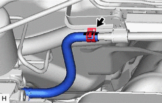
7. DISCONNECT NO. 2 BRAKE ACTUATOR HOSE
|
(a) Slide the clip and disconnect the No. 2 brake actuator hose from the No. 1 brake actuator tube. |
|
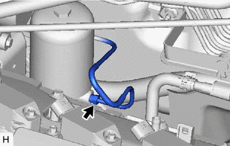
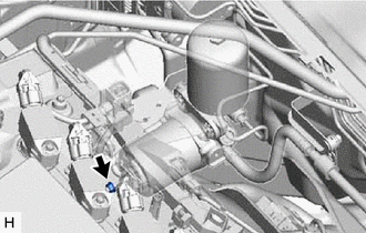
8. DISCONNECT ACCUMULATOR TO BRAKE MASTER CYLINDER TUBE
|
(a) Using a union nut wrench, disconnect the accumulator to brake master cylinder tube from the brake booster pump assembly. NOTICE:
|
|
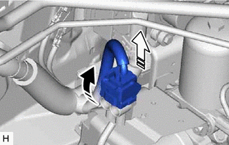
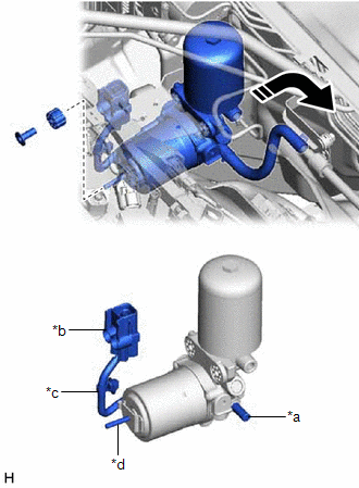
9. REMOVE BRAKE BOOSTER PUMP ASSEMBLY
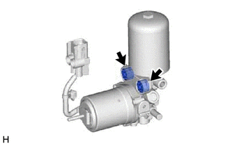
(a) Release the lock lever and disconnect the connector from the brake booster pump assembly as shown in the illustration.

|
Release the lock lever |

|
Disconnect the connector |
NOTICE:
Be careful not to allow any brake fluid to enter the connector.
|
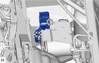
(b) Disengage the claw and clamp to separate the brake booster pump assembly wire harness from the brake actuator bracket assembly. |
|
|
(c) Remove the nut from the brake booster pump assembly. |
|
(d) Remove the brake booster pump assembly, brake booster pump bushing and brake actuator case collar from the brake actuator bracket assembly as shown in the illustration.
NOTICE:
- Do not apply excessive force to the brake lines.
- Do not carry the brake booster pump assembly by the parts shown in the illustration.
- Do not drop the brake booster pump assembly when carrying it.
- Be careful not to allow brake fluid to enter the connector.
|
*a |
Union |
|
*b |
Connector |
|
*c |
Wire Harness |
|
*d |
Stud |
|
|
Remove in this Direction |
|
(e) Remove the 2 brake booster pump collars and 2 brake booster pump bushings from the brake booster pump assembly. HINT: Perform this procedure only when replacement of the brake booster pump collars or brake booster pump bushings is necessary. |
|
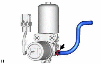
10. REMOVE NO. 2 BRAKE ACTUATOR HOSE
|
(a) Slide the clip and remove the No. 2 brake actuator hose from the brake booster pump assembly. |
|
|
|
|