| Last Modified: 08-21-2023 | 6.11:8.1.0 | Doc ID: RM100000001YN7E |
| Model Year Start: 2022 | Model: Avalon | Prod Date Range: [08/2021 - ] |
| Title: BRAKE SYSTEM (OTHER): BRAKE BOOSTER (for Gasoline Model): REMOVAL; 2022 MY Avalon [08/2021 - ] | ||
REMOVAL
CAUTION / NOTICE / HINT
The necessary procedures (adjustment, calibration, initialization or registration) that must be performed after parts are removed and installed, or replaced during brake booster assembly removal/installation are shown below.
Necessary Procedures After Parts Removed/Installed/Replaced
|
Replaced Part or Performed Procedure |
Necessary Procedure |
Effect/Inoperative Function when Necessary Procedure not Performed |
Link |
|---|---|---|---|
|
*: When performing learning using the Techstream.
Click here
|
|||
|
Battery terminal is disconnected/reconnected |
Perform steering sensor zero point calibration |
Lane Tracing Assist System |
|
|
Pre-collision system |
|||
|
Intelligent Clearance Sonar System* |
|||
|
Lighting System (for Gasoline Model with Cornering Light) |
|||
|
Memorize steering angle neutral point |
Parking assist monitor system |
|
|
|
Panoramic View Monitor System |
|
||
NOTICE:
Make sure to release vacuum from the brake booster assembly before removing the brake master cylinder sub-assembly from the brake booster assembly.
PROCEDURE
1. PRECAUTION
NOTICE:
After turning the engine switch off, waiting time may be required before disconnecting the cable from the negative (-) battery terminal. Therefore, make sure to read the disconnecting the cable from the negative (-) battery terminal notices before proceeding with work.
Click here
![2019 - 2022 MY Avalon Avalon HV [04/2018 - ]; INTRODUCTION: REPAIR INSTRUCTION: PRECAUTION](/t3Portal/stylegraphics/info.gif)
2. REMOVE BRAKE MASTER CYLINDER SUB-ASSEMBLY
Click here
3. REMOVE NO. 1 INSTRUMENT PANEL UNDER COVER SUB-ASSEMBLY
Click here
4. REMOVE COWL TOP VENTILATOR LOUVER SUB-ASSEMBLY
Click here
5. REMOVE FRONT CENTER UPPER SUSPENSION BRACE SUB-ASSEMBLY
Click here
6. REMOVE NO. 1 ENGINE COVER SUB-ASSEMBLY (for A25A-FKS)
Click here
7. REMOVE AIR CLEANER ASSEMBLY WITH AIR CLEANER HOSE (for A25A-FKS)
Click here
8. REMOVE AIR CLEANER ASSEMBLY WITH AIR CLEANER HOSE (for 2GR-FKS)
Click here
9. REMOVE BATTERY CLAMP SUB-ASSEMBLY
(a) for A25A-FKS:
|
(1) Disengage the 4 clamps from the battery clamp sub-assembly. |
|
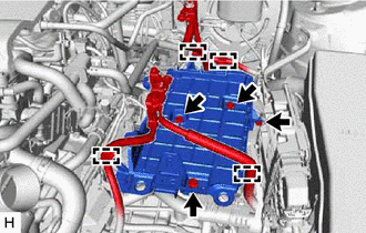
(2) Remove the 3 bolts, nut and battery clamp sub-assembly.
(b) for 2GR-FKS:
|
(1) Disengage the 5 clamps from the battery clamp sub-assembly. |
|
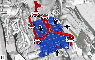
(2) Remove the 3 bolts, nut and battery clamp sub-assembly.
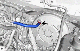
10. DISCONNECT UNION TO CHECK VALVE HOSE
|
(a) Slide the clip and disconnect the union to check valve hose from the brake booster assembly. |
|
11. LOOSEN LOCK NUT
|
(a) Loosen the lock nut of the brake master cylinder push rod clevis. |
|
12. REMOVE PUSH ROD PIN
Click here
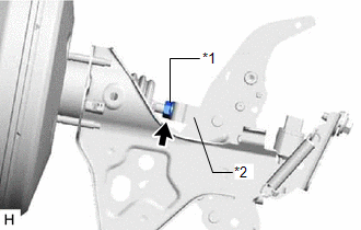
13. REMOVE BRAKE BOOSTER ASSEMBLY
|
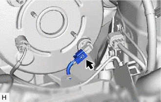
(a) Disconnect the connector from the vacuum warning switch assembly. |
|
|
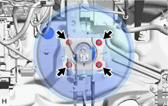
(b) Remove the 4 nuts and push the brake booster assembly toward the engine compartment. NOTICE: Do not apply excessive force to the brake lines. |
|
(c) Remove the brake master cylinder push rod clevis and lock nut from the brake booster assembly.
(d) Remove the brake booster assembly from the vehicle body.
NOTICE:
Do not apply excessive force to the brake lines.
14. REMOVE BRAKE BOOSTER GASKET
|
|
|