- Bleed air
- Clear the data stored during previous linear solenoid valve offset learning, ABS holding solenoid valve learning, brake pedal stroke sensor assembly zero point calibration and system information memorization
- Perform linear solenoid valve offset learning, ABS holding solenoid valve learning, brake pedal stroke sensor assembly zero point calibration and system information memorization
| Last Modified: 09-10-2025 | 6.11:8.1.0 | Doc ID: RM100000001YN7D |
| Model Year Start: 2022 | Model: Avalon HV | Prod Date Range: [08/2021 - ] |
| Title: BRAKE SYSTEM (OTHER): BRAKE BOOSTER (for HV Model): REMOVAL; 2022 MY Avalon HV [08/2021 - ] | ||
REMOVAL
CAUTION / NOTICE / HINT
The necessary procedures (adjustment, calibration, initialization, or registration) that must be performed after parts are removed, installed, or replaced during brake booster with master cylinder assembly removal/installation are shown below.
Necessary Procedures After Parts Removed/Installed/Replaced
|
Replaced Part or Performed Procedure |
Necessary Procedure |
Effect/Inoperative Function when Necessary Procedure not Performed |
Link |
|---|---|---|---|
|
Auxiliary battery terminal is disconnected/reconnected |
Perform steering sensor zero point calibration |
Lane Tracing Assist System |
|
|
Pre-collision System |
|||
|
Intelligent Clearance Sonar System* |
|||
|
Lighting System (for HV Model with Cornering Light) |
|||
|
Memorize steering angle neutral point |
Parking Assist Monitor System |
|
|
|
Panoramic View Monitor System |
|
||
|
Replacement of brake booster with master cylinder assembly |
|
|
for Initialization
for Calibration:
|
|
NOTICE:
While the auxiliary battery is connected, even if the power switch is off, the brake control system activates when the brake pedal is depressed or any door courtesy switch turns on. Therefore, when servicing the brake system components, do not operate the brake pedal or open/close the doors while the auxiliary battery is connected.
PROCEDURE
PROCEDURE
1. PRECAUTION
NOTICE:
After turning the power switch off, waiting time may be required before disconnecting the cable from the negative (-) auxiliary battery terminal. Therefore, make sure to read the disconnecting the cable from the negative (-) auxiliary battery terminal notices before proceeding with work.
Click here
![2019 - 2022 MY Avalon Avalon HV [04/2018 - ]; INTRODUCTION: REPAIR INSTRUCTION: PRECAUTION](/t3Portal/stylegraphics/info.gif)
2. PERFORM ACCUMULATOR PRESSURE ZERO DOWN
(a) Using the Techstream, perform the accumulator pressure zero down operation.
(1) Connect the Techstream to the DLC3 with the power switch off.
(2) Turn the power switch on (IG).
(3) Turn the Techstream on and enter the following menus: Chassis / ABS/VSC/TRAC / Utility / ECB (Electronically Controlled Brake system) Utility.
Chassis > ABS/VSC/TRAC > Utility
|
Tester Display |
|---|
|
ECB Utility |
(4) Select "Motor Invalid" on the "ECB (Electronically Controlled Brake system) Utility" screen.
(5) Perform "Motor Invalid" according to the display on the Techstream.
(6) Enter the following menus: Chassis / ABS/VSC/TRAC / Utility / ECB (Electronically Controlled Brake system) Utility.
Chassis > ABS/VSC/TRAC > Utility
|
Tester Display |
|---|
|
ECB Utility |
(7) Select "ECB (Electronically Controlled Brake system) Invalid" on the "ECB (Electronically Controlled Brake system) Utility" screen.
(8) Perform "ECB (Electronically Controlled Brake system) Invalid" according to the display on the Techstream.
(9) Depress the brake pedal 40 times or more to return all the fluid in the accumulator back to the reservoir.
HINT:
A buzzer may sound due to low accumulator pressure. As this is not a malfunction, continue the procedure.
(10) Check that the brake pedal is firm.
NOTICE:
If the brake pedal is not firm or the pump motor continues to operate even after depressing the brake pedal 40 times or more, the accumulator pressure zero down operation is not complete.
(11) Turn the Techstream off and turn the power switch off.
(12) Disconnect the Techstream from the DLC3.
(13) Disconnect the cable from the negative (-) auxiliary battery terminal.
Click here
(b) When the accumulator pressure zero down could not be performed using the Techstream.
NOTICE:
If DTCs are output, the accumulator pressure zero down operation may not be complete. In this case, perform the following procedure.
(1) With the power switch off, release the lock lever and disconnect the brake booster pump assembly connector as shown in the illustration.
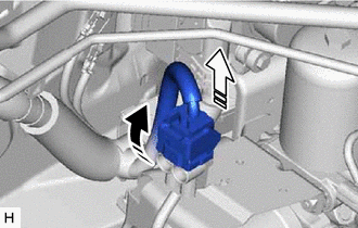

|
Release the lock lever |

|
Disconnect the connector |
NOTICE:
Be careful not to allow any brake fluid to enter the connector.
(2) Depress the brake pedal 40 times or more to return all the fluid in the accumulator back to the reservoir.
(3) Check that the brake pedal is firm.
NOTICE:
If the brake pedal is not firm or the pump motor continues to operate even after depressing the brake pedal 40 times or more, the accumulator pressure zero down operation is not complete.
(4) Disconnect the cable from the negative (-) auxiliary battery terminal.
Click here
3. REMOVE COWL TOP VENTILATOR LOUVER SUB-ASSEMBLY
Click here
4. REMOVE FRONT CENTER UPPER SUSPENSION BRACE SUB-ASSEMBLY
|
(a) Disconnect the connector. |
|
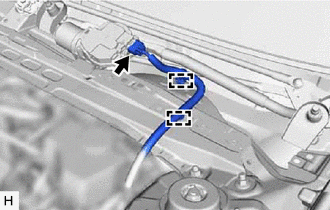
(b) Disengage the 2 clamps and separate the wire harness.
|
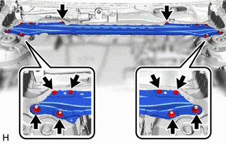
(c) Remove the 6 bolts, 4 nuts and front center upper suspension brace sub-assembly. |
|
5. DRAIN BRAKE FLUID
NOTICE:
If brake fluid leaks onto any painted surface, immediately wash it off.
6. DISCONNECT ENGINE ROOM MAIN WIRE
|
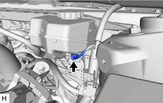
(a) Disconnect the connector from the brake booster with master cylinder assembly. |
|
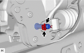
(b) Push the lock arm of the connector to disengage the lock and release the lock lever as shown in the illustration.
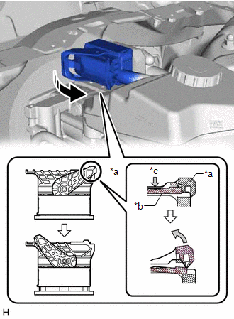
|
*a |
Lock Lever |
|
*b |
Lock Arm |
|
*c |
Push |
|
|
Release the lock lever |
(c) Using a screwdriver, release the pre-lock and disconnect the connector from the brake booster with master cylinder assembly as shown in the illustration.
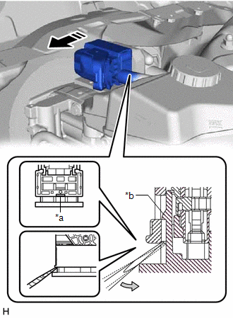
|
*a |
Screwdriver Insertion Point |
|
*b |
Pre-lock |
|
|
Disconnect the connector |
NOTICE:
Be careful not to allow any brake fluid to enter the connector.
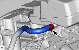
7. DISCONNECT NO. 1 BRAKE ACTUATOR HOSE
|
(a) Slide the clip and disconnect the No. 1 brake actuator hose from the brake booster with master cylinder assembly. |
|
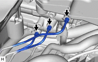
8. DISCONNECT BRAKE LINE
|
(a) Using a union nut wrench, disconnect the 3 brake lines from the brake booster with master cylinder assembly. NOTICE:
|
|
9. REMOVE NO. 1 INSTRUMENT PANEL UNDER COVER SUB-ASSEMBLY
Click here
10. REMOVE PUSH ROD PIN
|
(a) Remove the clip and push rod pin. |
|
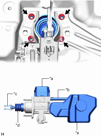
11. REMOVE BRAKE BOOSTER WITH MASTER CYLINDER ASSEMBLY
|
(a) Remove the 4 nuts and brake booster with master cylinder assembly. NOTICE:
|
|
12. REMOVE BRAKE MASTER CYLINDER GASKET
|
|
|