- Measure ultrasonic sensor detection angle
- Ultrasonic sensor detection angle registration
| Last Modified: 08-21-2023 | 6.11:8.1.0 | Doc ID: RM100000001YL5I |
| Model Year Start: 2022 | Model: Avalon | Prod Date Range: [08/2021 - ] |
| Title: 2GR-FKS (BATTERY / CHARGING): GENERATOR: REMOVAL; 2022 MY Avalon [08/2021 - ] | ||
REMOVAL
CAUTION / NOTICE / HINT
The necessary procedures (adjustment, calibration, initialization or registration) that must be performed after parts are removed and installed, or replaced generator assembly removal/installation are shown below.
Necessary Procedures After Parts Removed/Installed/Replaced
|
Replaced Part or Performed Procedure |
Necessary Procedure |
Effect/Inoperative Function when Necessary Procedure not Performed |
Link |
|---|---|---|---|
| *: When performing learning using the Techstream. | |||
|
Battery terminal is disconnected/reconnected |
Perform steering sensor zero point calibration |
Lane Tracing Assist System |
|
|
Pre-collision system |
|||
|
Intelligent clearance sonar system* |
|||
|
Lighting System (for Gasoline Model with Cornering Light) |
|||
|
Memorize steering angle neutral point |
Parking assist monitor system |
||
|
Panoramic view monitor system |
|||
|
Front bumper assembly (w/ Panoramic view monitor system) |
Front television camera view adjustment |
Panoramic view monitor system |
|
|
Front bumper assembly (w/ Intuitive Parking Assist System) |
|
|
|
PROCEDURE
1. PRECAUTION
NOTICE:
After turning the engine switch off, waiting time may be required before disconnecting the cable from the negative (-) battery terminal. Therefore, make sure to read the disconnecting the cable from the negative (-) battery terminal notices before proceeding with work.
2. DISCONNECT CABLE FROM NEGATIVE BATTERY TERMINAL
NOTICE:
When disconnecting the cable, some systems need to be initialized after the cable is reconnected.
3. REMOVE RADIATOR ASSEMBLY
4. REMOVE V-BANK COVER SUB-ASSEMBLY
5. REMOVE V-RIBBED BELT
6. REMOVE GENERATOR ASSEMBLY
|
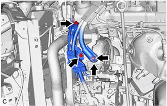
(a) Open the terminal cap. |
|
(b) Remove the nut and disconnect the wire harness from terminal B.
(c) Remove the 2 bolts.
|
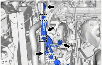
(d) Disconnect the generator assembly connector. |
|
(e) Disconnect the compressor assembly with magnetic clutch connector.
(f) Disconnect the camshaft timing oil control solenoid assembly connector.
(g) Disengage the 3 wire harness clamps and remove the wire harness clamp bracket.
|
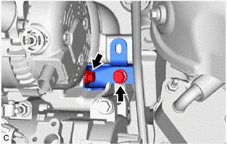
(h) Remove the 2 bolts and generator assembly bracket. |
|
|
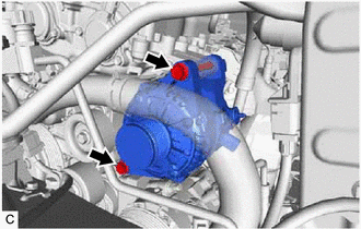
(i) Remove the 2 bolts and generator assembly. |
|
|
|
|
![2019 - 2022 MY Avalon [04/2018 - ]; PARK ASSIST / MONITORING: INTELLIGENT CLEARANCE SONAR SYSTEM (for Gasoline Model): CALIBRATION](/t3Portal/stylegraphics/info.gif)


