- Replacement of engine assembly
- Gas leak from exhaust system is repaired
- Replacement of engine coolant temperature sensor
| Last Modified: 08-21-2023 | 6.11:8.1.0 | Doc ID: RM100000001YL2E |
| Model Year Start: 2022 | Model: Avalon HV | Prod Date Range: [08/2021 - ] |
| Title: A25A-FXS (ENGINE MECHANICAL): ENGINE ASSEMBLY: REMOVAL; 2022 MY Avalon HV [08/2021 - ] | ||
REMOVAL
CAUTION / NOTICE / HINT
The necessary procedures (adjustment, calibration, initialization, or registration) that must be performed after parts are removed and installed, or replaced during engine assembly removal/installation are shown below.
Necessary Procedure After Parts Removed/Installed/Replaced
|
Replaced Part or Performed Procedure |
Necessary Procedure |
Effect/Inoperative Function when Necessary Procedure not Performed |
Link |
|---|---|---|---|
|
Auxiliary battery terminal is disconnected/reconnected |
Perform steering sensor zero point calibration |
Lane Tracing Assist System |
|
|
Pre-collision System |
|||
|
Intelligent clearance sonar system* |
|||
|
Lighting System (for HV Model with Cornering Light) |
|||
|
Memorize steering angle neutral point |
Parking assist monitor system |
|
|
|
Panoramic view monitor system |
|
||
|
Replacement of ECM |
Perform Vehicle Identification Number (VIN) registration |
MIL illuminates |
|
|
|
Inspection After Repair |
|
|
|
Replacement of inverter with converter assembly |
Resolver learning |
|
|
|
Replacement of hybrid vehicle transaxle assembly |
|
||
|
Front wheel alignment adjustment |
|
|
|
|
|
|
|
|
Suspension, tires, etc.*1 |
Rear television camera assembly optical axis (Back camera position setting) |
Parking assist monitor system |
|
|
Replacement of front bumper assembly |
Front television camera view adjustment |
Panoramic view monitor system |
|
|
Suspension, tires, etc.*1 |
|
||
|
Synchronize the vehicle information |
Lighting system (for HV Model with Cornering Light) |
|
-
*: When performing learning using the Techstream.
Click here
![2019 - 2022 MY Avalon HV [04/2018 - ]; PARK ASSIST / MONITORING: INTELLIGENT CLEARANCE SONAR SYSTEM (for HV Model): CALIBRATION](/t3Portal/stylegraphics/info.gif)
- *1: If the vehicle height has changed due to suspension or tire replacement
CAUTION:
-
The engine assembly with transaxle is very heavy. Be sure to follow the procedure described in the repair manual, or the engine lifter may suddenly drop or the engine assembly with transaxle may fall off the engine lifter.
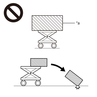
*a
An Object Exceeding Weight Limit of Engine Lifter
-
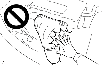
To prevent burns, do not touch the engine, exhaust manifold or other high temperature components while the engine is hot.
PROCEDURE
1. PRECAUTION
NOTICE:
After turning the power switch off, waiting time may be required before disconnecting the cable from the negative (-) auxiliary battery terminal. Therefore, make sure to read the disconnecting the cable from the negative (-) auxiliary battery terminal notices before proceeding with work.
Click here
2. RECOVER REFRIGERANT FROM REFRIGERATION SYSTEM
Click here
3. DISCHARGE FUEL SYSTEM PRESSURE
Click here
4. ALIGN FRONT WHEELS FACING STRAIGHT AHEAD
5. SECURE STEERING WHEEL
Click here
6. REMOVE FRONT WHEELS
Click here
7. REMOVE FRONT WHEEL OPENING EXTENSION PAD LH
(a) Remove the 3 screws and front wheel opening extension pad LH.
8. REMOVE FRONT WHEEL OPENING EXTENSION PAD RH
(a) Remove the 3 screws and front wheel opening extension pad RH.
9. REMOVE NO. 1 ENGINE UNDER COVER
(a) Remove the bolt, 2 clips, 6 screws and No. 1 engine under cover.
10. REMOVE NO. 2 ENGINE UNDER COVER ASSEMBLY
(a) Remove the 4 screws, 6 clips and No. 2 engine under cover assembly.
11. REMOVE FRONT FENDER APRON SEAL LH
(a) Remove the 2 screws, clip and front fender apron seal LH.
12. REMOVE FRONT FENDER APRON SEAL RH
(a) Remove the 2 screws, clip and front fender apron seal RH.
13. REMOVE HEADLIGHT ASSEMBLY
Click here
14. REMOVE FRONT LOWER BUMPER ABSORBER
|
(a) Remove the 4 bolts. |
|
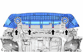
(b) Disengage the 2 claws to remove the front lower bumper absorber.
15. DRAIN ENGINE COOLANT
Click here
16. DRAIN ENGINE OIL
Click here
17. DRAIN HYBRID TRANSAXLE FLUID
Click here
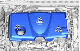
18. REMOVE NO. 1 ENGINE COVER SUB-ASSEMBLY
|
(a) Lift the front of the No. 1 engine cover sub-assembly to disengage the 2 clips, and then lift the rear of the No. 1 engine cover sub-assembly to disengage the clip and remove the No. 1 engine cover sub-assembly. NOTICE: Attempting to disengage both front and rear clips at the same time may cause the No. 1 engine cover sub-assembly to break. |
|
19. REMOVE INVERTER WITH CONVERTER ASSEMBLY
Click here
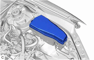
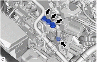
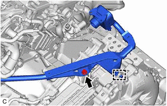
20. REMOVE INVERTER RESERVE TANK ASSEMBLY
|
(a) Remove the bolt. |
|
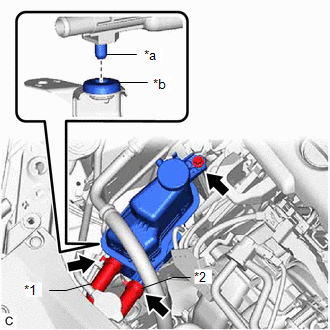
(b) Disengage the pin and remove the inverter reserve tank assembly.
(c) Slide the clip and disconnect the No. 5 inverter cooling hose from the inverter reserve tank assembly.
(d) Slide the clip and disconnect the No. 2 inverter cooling hose from the inverter reserve tank assembly.
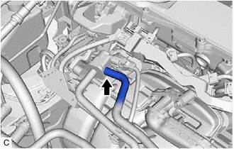
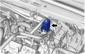
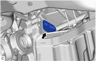
21. DISCONNECT NO. 1 FUEL VAPOR FEED HOSE
|
(a) Slide the clip and disconnect the No. 1 fuel vapor feed hose from the No. 1 vacuum switching valve assembly. |
|
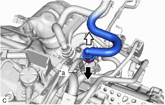
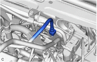
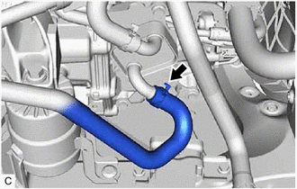
22. DISCONNECT OUTLET HEATER HOSE
(a) Pull out the retainer to disengage the lock claws and pull off the outlet heater hose from the No. 2 water by-pass pipe sub-assembly.
|
*a |
Retainer |

|
Pull out |

|
Pull off |
(b) Check that there is no foreign matter on the sealing surfaces of the disconnected water lines. Clean them if necessary.
(c) Cover the disconnected No. 2 water by-pass pipe sub-assembly and outlet heater hose connector with plastic bags to prevent damage and contamination.
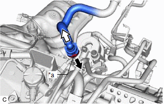
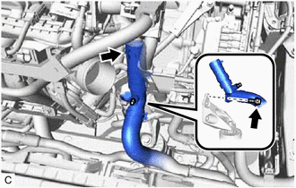
23. DISCONNECT INLET HEATER HOSE
(a) Pull out the retainer to disengage the lock claws and pull off the inlet heater hose from the flow shutting valve (water by-pass hose assembly).
|
*a |
Retainer |
|
|
Pull out |
|
|
Pull off |
(b) Check that there is no foreign matter on the sealing surfaces of the disconnected water lines. Clean them if necessary.
(c) Cover the disconnected flow shutting valve (water by-pass hose assembly) and inlet heater hose connector with plastic bags to prevent damage and contamination.
24. DISCONNECT FUEL TUBE SUB-ASSEMBLY
|
(a) Remove the No. 1 fuel pipe clamp from the fuel tube connector. |
|
(b) Disconnect the fuel tube sub-assembly.
|
(1) Disconnect the fuel tube sub-assembly from the fuel pipe. Click here
|
|
25. REMOVE NO. 2 ENGINE COOLANT TEMPERATURE SENSOR
Click here
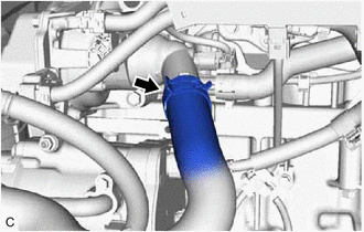
26. DISCONNECT NO. 1 RADIATOR HOSE
|
(a) Slide the clip and disconnect the No. 1 radiator hose from the water outlet. |
|
(b) Remove the bolt to disconnect the No. 1 radiator hose from the front engine mounting bracket.
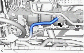
27. DISCONNECT NO. 2 RADIATOR HOSE
|
(a) Slide the clip and disconnect the No. 2 radiator hose from the water inlet. |
|
28. DISCONNECT NO. 1 COOLER REFRIGERANT DISCHARGE HOSE SUB-ASSEMBLY
Click here
29. DISCONNECT SUCTION HOSE SUB-ASSEMBLY
Click here
30. DISCONNECT NO. 5 INVERTER COOLING HOSE
|
(a) Slide the clip and disconnect the No. 5 inverter cooling hose from the motor cooling cooler. |
|
31. DISCONNECT WIRE HARNESS
HINT:
After disconnecting the wire harness, secure it with tape or equivalent to keep it out of the way.
|
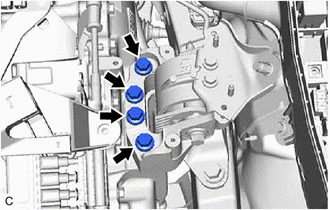
(a) Remove the No. 2 relay block cover from the engine room relay block and junction block assembly. |
|
|
(b) Remove the nut from the engine room relay block and junction block assembly. |
|
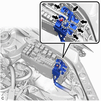
(c) Disconnect the 5 connectors from the engine room relay block and junction block assembly.
(d) Using a screwdriver, disengage the claw and disconnect the wire harness from the engine room relay block and junction block assembly.
|
(e) Remove the 2 bolts and disengage the earth wire. |
|
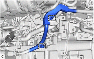
32. DISCONNECT NO. 5 WATER BY-PASS HOSE
|
(a) Slide the clip and disconnect the No. 5 water by-pass hose from the No. 3 water by-pass pipe. |
|
33. SEPARATE STEERING INTERMEDIATE SHAFT ASSEMBLY
Click here
34. REMOVE FRONT EXHAUST PIPE ASSEMBLY (TWC: Rear Catalyst)
Click here
35. REMOVE FRONT DRIVE SHAFT ASSEMBLY
Click here
36. REMOVE ENGINE ASSEMBLY WITH TRANSAXLE
(a) Set the engine assembly with transaxle on an engine lifter.
NOTICE:
- Using height adjustment attachments and plate lift attachments, keep the engine assembly with transaxle level.
- Do not perform any procedures while the engine assembly is suspended because doing so may cause the engine assembly to drop, resulting in injury. However, the engine assembly needs to be suspended when it is installed to or removed from an engine stand.
- To prevent the engine assembly from unexpectedly moving, securely support the engine assembly until it is secured to an engine stand.
|
(b) Remove the 6 bolts and body mounting plate. |
|
|
(c) Remove the 3 bolts and nut and separate the engine mounting insulator sub-assembly RH from the engine mounting bracket RH. |
|
|
(d) Remove the 3 bolts and remove the engine mounting stay LH from the engine mounting insulator LH. |
|
|
(e) Remove the 4 bolts and separate the engine mounting insulator LH from the hybrid vehicle transaxle assembly. |
|
|
|
Bolt |
|
|
Nut |
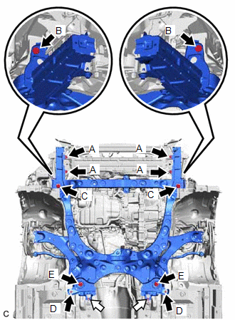
(f) Remove the 4 bolts (A), 2 bolts (B) and 2 bolts (C) and front bumper extension sub-assembly RH and front bumper extension sub-assembly LH from the front frame assembly and vehicle body.
(g) Remove the 2 bolts (D), 2 bolts (E) and 2 nuts and front suspension member bracket sub-assembly RH and front suspension member bracket sub-assembly LH from the front frame assembly and vehicle body.
(h) Operate the engine lifter and remove the engine assembly with transaxle from the vehicle.
NOTICE:
- Make sure that the engine assembly with transaxle is clear of all wiring and hoses.
- While lowering the engine assembly with transaxle from the vehicle, do not allow it to contact the vehicle.
37. REMOVE FUEL DELIVERY GUARD
|
(a) Remove the bolt and fuel delivery guard from the engine mounting bracket RH. |
|
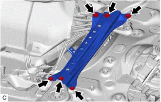
38. INSTALL ENGINE HANGERS
|
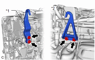
(a) Install the No. 1 engine hanger and No. 2 engine hanger with the 4 bolts as shown in the illustration. Torque: 43 N·m {438 kgf·cm, 32 ft·lbf}
|
|
(b) Using an engine sling device and engine lift, secure the engine assembly with transaxle.
NOTICE:
- Pay attention to the angle of the sling device as the engine assembly or No. 1 engine hanger and No. 2 engine hanger may be damaged or deformed if the angle is incorrect.
- Do not perform any procedures while the engine assembly is suspended because doing so may cause the engine assembly to drop, resulting in injury. However, the engine assembly needs to be suspended when it is installed to or removed from an engine stand.
39. REMOVE FLYWHEEL HOUSING UNDER COVER
|
(a) Remove the flywheel housing under cover from the cylinder block sub-assembly. |
|
40. REMOVE STEERING GEAR HEAT INSULATOR
Click here
41. REMOVE ENGINE WIRE
(a) Disconnect all clamps and connectors and remove the engine wire from the engine assembly with transaxle.
42. REMOVE FRONT FRAME ASSEMBLY
Click here
43. REMOVE FRONT ENGINE MOUNTING INSULATOR
HINT:
Perform this procedure only when replacement of the front engine mounting insulator is necessary.
Click here
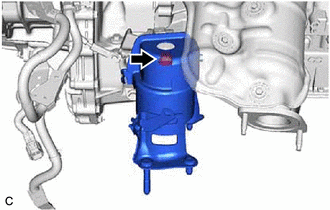
44. REMOVE REAR ENGINE MOUNTING INSULATOR
HINT:
Perform this procedure only when replacement of the rear engine mounting insulator is necessary.
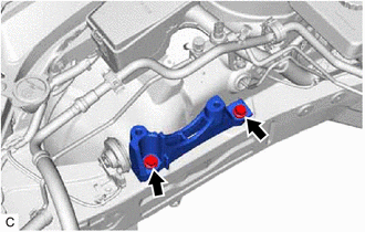
|
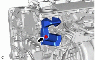
(a) Remove the bolt and rear engine mounting insulator from the rear engine mounting bracket. |
|
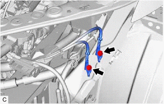
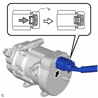
45. REMOVE HV AIR CONDITIONING WIRE
|
(a) Disengage the 2 clamps. |
|
(b) Using a screwdriver, slide the green-colored lock of the connector as shown in the illustration to release it and disconnect the connector.
|
*a |
Green-colored Lock |

|
Slide |
CAUTION:
Make sure to wear insulated gloves.
NOTICE:
Insulate the disconnected terminals and connector with insulating tape.
|
(c) Remove the bolt. |
|
(d) Disengage the guide to remove the HV air conditioning wire from the hybrid vehicle transaxle assembly.
46. REMOVE STARTER HOLE INSULATOR
Click here
47. REMOVE FLYWHEEL HOUSING SIDE COVER
Click here
48. REMOVE HYBRID VEHICLE TRANSAXLE ASSEMBLY
Click here
49. REMOVE TRANSMISSION INPUT DAMPER ASSEMBLY
Click here
50. REMOVE FLYWHEEL SUB-ASSEMBLY
Click here
51. REMOVE NO. 1 CRANKSHAFT POSITION SENSOR PLATE
Click here
52. INSTALL ENGINE ASSEMBLY TO ENGINE STAND
(a) Install the engine assembly to an engine stand.
53. REMOVE ENGINE HANGERS
(a) Remove the 4 bolts, No. 1 engine hanger and No. 2 engine hanger from the cylinder head sub-assembly and engine mounting bracket RH.
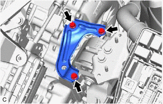
54. REMOVE ENGINE MOUNTING INSULATOR SUB-ASSEMBLY RH
HINT:
Perform this procedure only when replacement of the engine mounting insulator sub-assembly RH is necessary.
|
(a) Disengage the No. 6 water by-pass hose. |
|
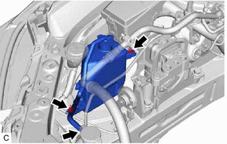
(b) Remove the bolt, nut and the radiator reserve tank assembly.
|
(c) Disengage the clamp. |
|

(d) Remove the bolt and disconnect the cooler bracket from the engine mounting insulator sub-assembly RH.
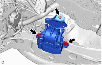
(e) Remove the 2 bolts and nut and remove the engine mounting insulator sub-assembly RH.
55. REMOVE ENGINE MOUNTING SPACER
HINT:
Perform this procedure only when replacement of the engine mounting spacer is necessary.
|
(a) Remove the 2 bolts and engine mounting spacer from the vehicle body. |
|
56. REMOVE ENGINE MOUNTING INSULATOR LH
HINT:
Perform this procedure only when replacement of the engine mounting insulator LH is necessary.
|
(a) Remove the 2 bolts, nut and the engine mounting insulator LH. |
|
|
|
|