| Last Modified: 08-21-2023 | 6.11:8.1.0 | Doc ID: RM100000001YKOX |
| Model Year Start: 2022 | Model: Avalon HV | Prod Date Range: [08/2021 - ] |
| Title: P710 (HYBRID TRANSMISSION / TRANSAXLE): SHIFT PADDLE SWITCH: REMOVAL; 2022 MY Avalon HV [08/2021 - ] | ||
REMOVAL
CAUTION / NOTICE / HINT
The necessary procedures (adjustment, calibration, initialization, or registration) that must be performed after parts are removed and installed, or replaced during shift paddle switch (transmission shift switch assembly) removal/installation are shown below.
Necessary Procedures After Parts Removed/Installed/Replaced
|
Replaced Part or Performed Procedure |
Necessary Procedure |
Effect/Inoperative Function when Necessary Procedure not Performed |
Link |
|---|---|---|---|
| *: When performing learning using the Techstream. | |||
|
Auxiliary battery terminal is disconnected/reconnected |
Perform steering sensor zero point calibration |
Lane Tracing Assist System |
|
|
Pre-collision System |
|||
|
Intelligent clearance sonar system* |
|||
|
Lighting system (w/ AFS)(EXT) |
|||
|
Memorize steering angle neutral point |
Parking assist monitor system |
||
|
Panoramic view monitor system |
|||
NOTICE:
- Do not remove/install the spiral cable with sensor sub-assembly with the battery connected and the power switch on (IG).
- Do not rotate the spiral cable with sensor sub-assembly without the steering wheel assembly installed, with the battery connected and the power switch on (IG).
- Ensure that the steering wheel assembly is installed and aligned straight when inspecting the steering sensor.
PROCEDURE
1. REMOVE STEERING WHEEL ASSEMBLY
2. REMOVE STEERING PAD SWITCH ASSEMBLY
3. REMOVE SHIFT PADDLE SWITCH (TRANSMISSION SHIFT SWITCH ASSEMBLY)
|
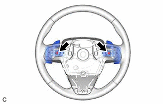
(a) Remove the 2 screws. |
|
|
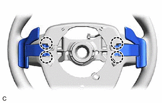
(b) Disengage the 4 claws. |
|
|
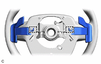
(c) Disengage the 2 clamps to disconnect the shift paddle switch (transmission shift switch assemby) from the steering wheel assembly. |
|
|
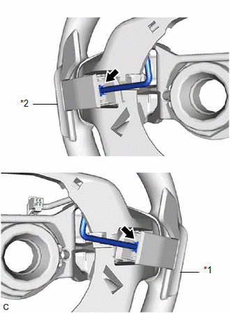
(d) Disconnect the No. 1 transmission shift switch assembly connector and No. 2 transmission shift switch assembly connector to remove the No. 1 transmission shift switch assembly and No. 2 transmission shift switch assembly from the No. 1 switch wire. |
|
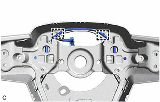
4. REMOVE NO. 1 SWITCH WIRE
HINT:
Perform this procedure only when replacement of the No. 1 switch wire is necessary.
|
(a) Disengage the 2 guides and remove the No. 1 switch wire from the steering wheel assembly. |
|
|
|
|
![2019 - 2022 MY Avalon HV [04/2018 - ]; PARK ASSIST / MONITORING: INTELLIGENT CLEARANCE SONAR SYSTEM (for HV Model): CALIBRATION](/t3Portal/stylegraphics/info.gif)
