| Last Modified: 08-21-2023 | 6.11:8.1.0 | Doc ID: RM100000001XWFE |
| Model Year Start: 2022 | Model: Avalon | Prod Date Range: [08/2021 - ] |
| Title: METER / GAUGE / DISPLAY: METER / GAUGE SYSTEM (for Gasoline Model): Fuel Receiver Gauge Display Malfunction; 2022 MY Avalon [08/2021 - ] | ||
|
Fuel Receiver Gauge Display Malfunction |
DESCRIPTION
FUEL RECEIVER GAUGE OPERATION
The combination meter assembly receives the fuel level signal via direct line from the fuel sender gauge assembly and No. 2 fuel sender gauge assembly* and the fuel consumption signal from the ECM via CAN communication, then calculates the fuel level in the fuel tank and displays the calculated value on the fuel receiver gauge.
- *: for AWD
FUEL RECEIVER GAUGE READING
(a) During normal driving:
During driving, the value of the fuel receiver gauge is updated based on the reduction in the fuel level. The reduction is calculated by deducting the value calculated based on the fuel consumption signal sent by the ECM from the value calculated based on the signal sent by the fuel sender gauge assembly and No. 2 fuel sender gauge assembly*.
- *: for AWD
(b) During refueling:
As the fuel level in the fuel tank increases during refilling, the output value of the fuel sender gauge assembly and No. 2 fuel sender gauge assembly* changes. When the combination meter assembly detects a change in the output value of the fuel sender gauge assembly and No. 2 fuel sender gauge assembly* of a certain value or more, it determines that fuel is being added and calculates the added amount. This control is called refueling judgment and the fuel receiver gauge display is updated in accordance with the fuel level calculated based on the refueling judgment.
- *: for AWD
NOTICE:
Add fuel with the engine switch off to ensure safety and to enable refueling judgment so that an appropriate fuel receiver gauge reading will be obtained.
REFUELING JUDGMENT CONDITIONS
(a) Normal judgment condition (When normal refueling method is used)
-
With the engine switch off, the fuel sender gauge assembly and No. 2 fuel sender gauge assembly* detects a change of 5.0 liters (5.3 US qts, 4.4 Imp. qts) or more in the fuel level.
- *: for AWD
(b) Other judgment conditions (When other refueling method is used)
Any of the following conditions is met:
- With the vehicle and engine stopped and the engine switch on (IG), the fuel sender gauge assembly and No. 2 fuel sender gauge assembly* detects a change of 5.0 liters (5.3 US qts, 4.4 Imp. qts) or more in the fuel level.
- With the vehicle stopped, the engine switch on (IG) and the shift lever in P or N, the fuel sender gauge assembly and No. 2 fuel sender gauge assembly* detects a change of 5.0 liters (5.3 US qts, 4.4 Imp. qts) or more in the fuel level.
-
With the vehicle stopped, the engine switch on (IG) and the shift lever not in P or N, the fuel sender gauge assembly and No. 2 fuel sender gauge assembly* detects a change of 15.0 liters (15.9 US qts, 13.2 Imp. qts) or more in the fuel level.
- *: for AWD
PRECAUTION FOR REFUELING
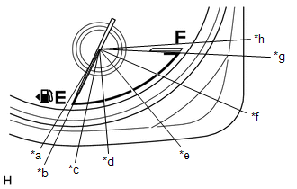
(a) The fuel sender gauge assembly and No. 2 fuel sender gauge assembly* cannot detect changes in the fuel level within certain ranges (around points E, 1/2* and F). Therefore, even if 5.0 liters (5.3 US qts, 4.4 Imp. qts) or more of fuel is added, refueling judgment may not be performed and the fuel receiver gauge reading may not change when fuel level is within such ranges.
- *: for AWD
(b) When refueling judgment is performed, it takes up to approximately 25 seconds for the fuel receiver gauge reading to change to the appropriate level.
FORCED RESET OF FUEL RECEIVER GAUGE
When driving at a vehicle speed of 20 km/h (12 mph) or more, if the fuel level calculated using the signal from the fuel sender gauge assembly and No. 2 fuel sender gauge assembly* is different from the fuel receiver gauge reading by 15.0 liters (15.9 US qts, 13.2 Imp. qts) or more for approximately 2 minutes, the fuel sender gauge assembly reading is immediately updated based on the calculated fuel level.
- *: for AWD
CAUTION / NOTICE / HINT
NOTICE:
- When replacing the combination meter assembly, always replace it with a new one. If a combination meter assembly which was installed to another vehicle is used, the information stored in it will not match the information from the vehicle and a DTC may be stored.
-
Before preforming this procedure, check for Meter / Gauge System DTC B150013 or B150113* which is stored if an open or short in the circuit is detected. If DTC B150013 or B150113* is output, perform troubleshooting and repairs as necessary.
Click here
![2021 - 2022 MY Avalon [08/2020 - ]; METER / GAUGE / DISPLAY: METER / GAUGE SYSTEM (for Gasoline Model): B150013,B150113; Fuel Sender Circuit Open](/t3Portal/stylegraphics/info.gif)
- *: for AWD
HINT:
When the fuel level drops below the following amount, the fuel level warning light illuminates.
- for 60.6 liter (64.0 US qts, 53.3 Imp. qts) Fuel Tank: 9.1 liter (9.6 US qts, 8.0 Imp. qts)
- for 55.0 liter (58.1 US qts, 48.4 Imp. qts) Fuel Tank: 8.3 liter (8.8 US qts, 7.3 Imp. qts)
PROCEDURE
|
1. |
CHECK CAN COMMUNICATION SYSTEM |
(a) Check if CAN communication DTCs are output.
Click here
|
Result |
Proceed to |
|---|---|
|
DTCs are not output |
A |
|
DTCs are output |
B |
| B |

|
|

|
2. |
CHECK FOR DTC (SFI SYSTEM) |
(a) Check if SFI system DTCs are output.
Powertrain > Engine > Trouble Codes
|
Result |
Proceed to |
|---|---|
|
DTCs are not output |
A |
|
DTCs are output |
B |
| B |
|
GO TO SFI SYSTEM for 2GR-FKS: Click here
for A25A-FKS: Click here
|
|
|
3. |
CHECK FOR DTC (ELECTRONICALLY CONTROLLED BRAKE SYSTEM) |
(a) Check if electronically controlled brake system DTCs are output.
Chassis > Brake/EPB > Trouble Codes
|
Result |
Proceed to |
|---|---|
|
DTCs are not output |
A |
|
DTCs are output |
B |
| B |
|
|
|
4. |
CHECK SYMPTOMS |
(a) Ask the customer about the problem symptoms.
|
Result |
Proceed to |
|---|---|
|
Malfunction occurs when adding fuel (Even after adding fuel, reading does not increase at all or increases very slowly, etc.) |
A |
|
Malfunction occurs during normal driving (The reading does not change, decreases quickly or decreases when the vehicle is not being driven, etc.) (The problem symptom recurs) |
B |
|
Malfunction occurs during normal driving (The reading does not change, decreases quickly or decreases when the vehicle is not being driven, etc.) (The problem symptom does not recur) |
C |
| B |
|
| C |
|
|
|
5. |
PERFORM ACTIVE TEST USING TECHSTREAM |
|
*a |
Fuel Gauge Operation (Sender E) |
|
*b |
Fuel Gauge Operation (Empty) |
|
*c |
Fuel Gauge Operation (Warning) |
|
*d |
Fuel Gauge Operation (1/4) |
|
*e |
Fuel Gauge Operation (1/2) |
|
*f |
Fuel Gauge Operation (3/4) |
|
*g |
Fuel Gauge Operation (Full) |
|
*h |
Fuel Gauge Operation (Sender F) |
(a) Connect the Techstream to the DLC3.
(b) Turn the engine switch on (IG).
(c) Turn the Techstream on.
(d) Enter following menus: Body Electrical / Combination Meter / Active Test.
(e) Perform the Active Test according to the display on the Techstream.
Body Electrical > Combination Meter > Active Test
|
Tester Display |
Measurement Item |
Control Range |
Diagnostic Note |
|---|---|---|---|
|
Fuel Gauge Operation (Sender E) |
Fuel receiver gauge (Sender E) |
ON |
- |
|
Fuel Gauge Operation (Empty) |
Fuel receiver gauge (Empty) |
ON |
- |
|
Fuel Gauge Operation (Warning) |
Fuel receiver gauge (Warning) |
ON |
- |
|
Fuel Gauge Operation (1/4) |
Fuel receiver gauge (1/4) |
ON |
- |
|
Fuel Gauge Operation (1/2) |
Fuel receiver gauge (1/2) |
ON |
- |
|
Fuel Gauge Operation (3/4) |
Fuel receiver gauge (3/4) |
ON |
- |
|
Fuel Gauge Operation (Full) |
Fuel receiver gauge (Full) |
ON |
- |
|
Fuel Gauge Operation (Sender F) |
Fuel receiver gauge (Sender F) |
ON |
- |
Body Electrical > Combination Meter > Active Test
|
Tester Display |
|---|
|
Fuel Gauge Operation (Sender E) |
Body Electrical > Combination Meter > Active Test
|
Tester Display |
|---|
|
Fuel Gauge Operation (Empty) |
Body Electrical > Combination Meter > Active Test
|
Tester Display |
|---|
|
Fuel Gauge Operation (Warning) |
Body Electrical > Combination Meter > Active Test
|
Tester Display |
|---|
|
Fuel Gauge Operation (1/4) |
Body Electrical > Combination Meter > Active Test
|
Tester Display |
|---|
|
Fuel Gauge Operation (1/2) |
Body Electrical > Combination Meter > Active Test
|
Tester Display |
|---|
|
Fuel Gauge Operation (3/4) |
Body Electrical > Combination Meter > Active Test
|
Tester Display |
|---|
|
Fuel Gauge Operation (Full) |
Body Electrical > Combination Meter > Active Test
|
Tester Display |
|---|
|
Fuel Gauge Operation (Sender F) |
OK:
Fuel receiver gauge indication is normal.
| NG |
|
|
|
6. |
CHECK FUEL RECEIVER GAUGE (OPERATION BY ADDING FUEL) |
(a) If the fuel tank assembly is almost full, drain 20 liters (21.1 US qts, 17.6 Imp. qts) or more of fuel.
HINT:
This is not necessary when the fuel tank assembly is sufficiently below full.
(b) Record the fuel receiver gauge reading.
(c) Turn the engine switch off.
(d) Disconnect the cable from the negative (-) battery terminal to reset the fuel receiver gauge.
(e) Connect the cable to the negative (-) battery terminal.
(f) Turn the engine switch on (IG).
(g) Drive the vehicle at 1.8 km/h (1 mph) or more, then stop the vehicle.
(h) Turn the engine switch off.
(i) Add 5.0 liters (5.3 US qts, 4.4 Imp. qts) or more of fuel.
(j) Turn the engine switch on (IG).
(k) Check that the fuel receiver gauge reading increases in proportion to the amount of fuel added.
|
Result |
Proceed to |
|---|---|
|
Fuel receiver gauge reading increases in proportion to the amount of fuel added |
A |
|
Fuel receiver gauge reading does not change even when fuel is added |
B |
| A |
|
| B |
|
|
7. |
PERFORM ACTIVE TEST USING TECHSTREAM |
|
*a |
Fuel Gauge Operation (Sender E) |
|
*b |
Fuel Gauge Operation (Empty) |
|
*c |
Fuel Gauge Operation (Warning) |
|
*d |
Fuel Gauge Operation (1/4) |
|
*e |
Fuel Gauge Operation (1/2) |
|
*f |
Fuel Gauge Operation (3/4) |
|
*g |
Fuel Gauge Operation (Full) |
|
*h |
Fuel Gauge Operation (Sender F) |
(a) Connect the Techstream to the DLC3.
(b) Turn the engine switch on (IG).
(c) Turn the Techstream on.
(d) Enter following menus: Body Electrical / Combination Meter / Active Test.
(e) Perform the Active Test according to the display on the Techstream.
Body Electrical > Combination Meter > Active Test
|
Tester Display |
Measurement Item |
Control Range |
Diagnostic Note |
|---|---|---|---|
|
Fuel Gauge Operation (Sender E) |
Fuel receiver gauge (Sender E) |
ON |
- |
|
Fuel Gauge Operation (Empty) |
Fuel receiver gauge (Empty) |
ON |
- |
|
Fuel Gauge Operation (Warning) |
Fuel receiver gauge (Warning) |
ON |
- |
|
Fuel Gauge Operation (1/4) |
Fuel receiver gauge (1/4) |
ON |
- |
|
Fuel Gauge Operation (1/2) |
Fuel receiver gauge (1/2) |
ON |
- |
|
Fuel Gauge Operation (3/4) |
Fuel receiver gauge (3/4) |
ON |
- |
|
Fuel Gauge Operation (Full) |
Fuel receiver gauge (Full) |
ON |
- |
|
Fuel Gauge Operation (Sender F) |
Fuel receiver gauge (Sender F) |
ON |
- |
Body Electrical > Combination Meter > Active Test
|
Tester Display |
|---|
|
Fuel Gauge Operation (Sender E) |
Body Electrical > Combination Meter > Active Test
|
Tester Display |
|---|
|
Fuel Gauge Operation (Empty) |
Body Electrical > Combination Meter > Active Test
|
Tester Display |
|---|
|
Fuel Gauge Operation (Warning) |
Body Electrical > Combination Meter > Active Test
|
Tester Display |
|---|
|
Fuel Gauge Operation (1/4) |
Body Electrical > Combination Meter > Active Test
|
Tester Display |
|---|
|
Fuel Gauge Operation (1/2) |
Body Electrical > Combination Meter > Active Test
|
Tester Display |
|---|
|
Fuel Gauge Operation (3/4) |
Body Electrical > Combination Meter > Active Test
|
Tester Display |
|---|
|
Fuel Gauge Operation (Full) |
Body Electrical > Combination Meter > Active Test
|
Tester Display |
|---|
|
Fuel Gauge Operation (Sender F) |
OK:
Fuel receiver gauge indication is normal.
| NG |
|
|
|
8. |
CHECK FUEL RECEIVER GAUGE |
(a) Record the fuel receiver gauge reading.
(b) Turn the engine switch off.
(c) Disconnect the cable from the negative (-) battery terminal to reset the fuel receiver gauge.
(d) Connect the cable to the negative (-) battery terminal.
(e) Turn the engine switch on (IG).
(f) Check if the fuel receiver gauge reading corresponds with the amount of fuel remaining in the fuel tank assembly.
|
Result |
Proceed to |
|---|---|
|
Fuel receiver gauge reading corresponds with the amount of fuel remaining in the fuel tank assembly |
A |
|
Fuel receiver gauge reading does not correspond with the amount of fuel remaining in the fuel tank assembly |
B |
| A |
|
| B |
|
|
9. |
INSPECT FUEL TANK ASSEMBLY |
HINT:
Inspect the fuel tank assembly, fuel sender assembly and No. 2 fuel sender gauge assembly* for deformation, foreign matter or an improperly installed fuel receiver gauge, as this may be the cause of the fuel receiver gauge malfunction.
- *: for AWD
(a) Visually check the fuel tank assembly for any abnormalities.
(b) Check if there is an excessive amount of foreign matter in the fuel tank assembly.
(c) Visually check the fuel sender gauge assembly and No. 2 fuel sender gauge assembly* for damage and confirm that it operates correctly.
(d) Check the installation condition of the fuel tank assembly fuel sender gauge assembly and No. 2 fuel sender gauge assembly*.
- *: for AWD
|
Result |
Proceed to |
|---|---|
|
Normal |
A |
|
Appearance of the fuel tank assembly is abnormal |
B |
|
There is an excessive amount of foreign matter in the fuel tank assembly |
C |
|
The fuel sender gauge assembly is visually damaged or does not operate correctly (for 2WD) |
D |
|
The fuel sender gauge assembly or No. 2 fuel sender gauge assembly is visually damaged or does not operate correctly (for AWD) |
E |
|
The fuel tank assembly or fuel sender gauge assembly is not installed correctly (for 2WD) |
F |
|
The fuel tank assembly, fuel sender gauge assembly or No. 2 fuel sender gauge assembly is not installed correctly (for AWD) |
G |
| A |
|
| B |
|
REPLACE FUEL TANK ASSEMBLY for 2GR-FKS: Click here
for A25A-FKS: Click here
|
| C |
|
CLEAN INSIDE OF FUEL TANK ASSEMBLY |
| D |
|
| E |
|
REPLACE FUEL SENDER GAUGE ASSEMBLY OR NO. 2 FUEL SENDER GAUGE ASSEMBLY |
| F |
|
INSTALL FUEL TANK ASSEMBLY OR FUEL SENDER GAUGE ASSEMBLY CORRECTLY |
| G |
|
INSTALL FUEL TANK ASSEMBLY, FUEL SENDER GAUGE ASSEMBLY OR NO. 2 FUEL SENDER GAUGE ASSEMBLY CORRECTLY |
|
|
|