- VSC is disabled or malfunctions
- DTCs are output
- Slip indicator light illuminates
- ABS warning light illuminates
| Last Modified: 09-10-2025 | 6.11:8.1.0 | Doc ID: RM100000001XT0Y |
| Model Year Start: 2022 | Model: Avalon | Prod Date Range: [08/2021 - ] |
| Title: BRAKE CONTROL / DYNAMIC CONTROL SYSTEMS: BRAKE ACTUATOR (for Gasoline Model): REMOVAL; 2022 MY Avalon [08/2021 - ] | ||
REMOVAL
CAUTION / NOTICE / HINT
The necessary procedures (adjustment, calibration, initialization or registration) that must be performed after parts are removed and installed, or replaced during brake actuator assembly removal/installation are shown below.
Necessary Procedures After Parts Removed/Installed/Replaced
|
Replaced Part or Performed Procedure |
Necessary Procedure |
Effect/Inoperative Function when Necessary Procedure not Performed |
Link |
|---|---|---|---|
|
*: When performing learning using the Techstream.
Click here
|
|||
|
Battery terminal is disconnected/reconnected |
Perform steering sensor zero point calibration |
Lane Tracing Assist System |
|
|
Pre-collision system |
|||
|
Intelligent Clearance Sonar System* |
|||
|
Lighting System (for Gasoline Model with Cornering Light) |
|||
|
Memorize steering angle neutral point |
Parking assist monitor system |
|
|
|
Panoramic View Monitor System |
|
||
|
Replacement of brake actuator assembly |
Perform acceleration sensor zero point calibration and system information memorization |
|
|
|
Operate the electric parking brake switch |
Electric Parking Brake System |
|
|
PROCEDURE
PROCEDURE
1. PRECAUTION
NOTICE:
After turning the engine switch off, waiting time may be required before disconnecting the cable from the negative (-) battery terminal. Therefore, make sure to read the disconnecting the cable from the negative (-) battery terminal notices before proceeding with work.
Click here
![2019 - 2022 MY Avalon Avalon HV [04/2018 - ]; INTRODUCTION: REPAIR INSTRUCTION: PRECAUTION](/t3Portal/stylegraphics/info.gif)
2. DISCONNECT CABLE FROM NEGATIVE BATTERY TERMINAL
for A25A-FKS: Click here
for 2GR-FKS: Click here
NOTICE:
When disconnecting the cable, some systems need to be initialized after the cable is reconnected.
Click here
3. DRAIN BRAKE FLUID
NOTICE:
If brake fluid leaks onto any painted surface, immediately wash it off.
4. REMOVE FRONT WHEEL RH
Click here
5. REMOVE COWL TOP VENTILATOR LOUVER SUB-ASSEMBLY
Click here
6. REMOVE FRONT CENTER UPPER SUSPENSION BRACE SUB-ASSEMBLY
|
(a) Disconnect the connector. |
|
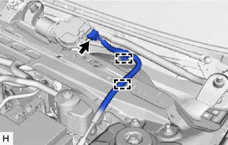
(b) Disengage the 2 clamps and separate the wire harness.
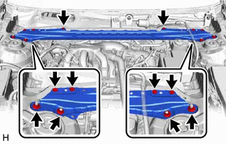
|
(c) Remove the 6 bolts, 4 nuts and front center upper suspension brace sub-assembly. |
|
7. REMOVE BRAKE ACTUATOR WITH BRACKET
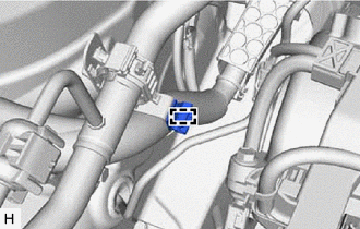
(a) Release the lock lever and disconnect the connector from the brake actuator assembly.

|
Release the lock lever |

|
Disconnect the connector |
NOTICE:
Be careful not to allow any brake fluid to enter the connector.
|
(b) Use tags or make a memo to identify the places to reconnect the brake lines. |
|
|
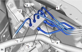
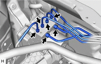
(c) Using a union nut wrench, disconnect the 6 brake lines from the brake actuator assembly. NOTICE:
|
|
|
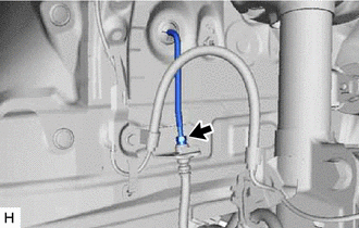
(d) Using a union nut wrench, disconnect the front No. 3 brake tube while holding the front flexible hose with a wrench. NOTICE:
|
|
|
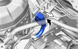
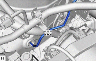
(e) Disengage the clamp and separate the front No. 3 brake tube. NOTICE: Do not kink or damage the front No. 3 brake tube. |
|
|
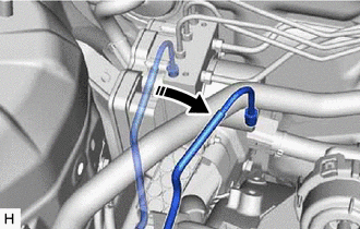
(f) Move aside the front No. 3 brake tube as shown in the illustration. NOTICE: Do not apply excessive force to the front No. 3 brake tube. |
|
|
(g) Disengage the clamp and remove the brake tube clamp. |
|
(h) Apply protective tape to the vehicle body as shown in the illustration.
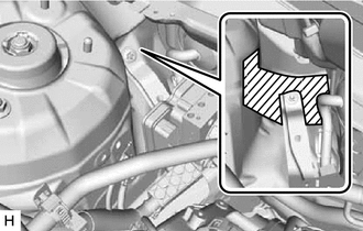

|
Protective Tape |
|
(i) Remove the 2 bolts. HINT: Insert the tool from the bottom of the vehicle. |
|
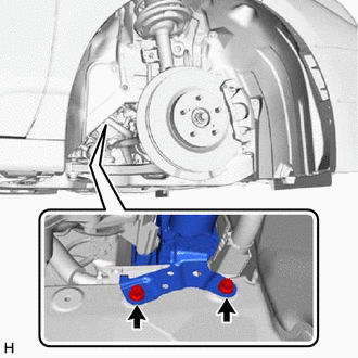
|
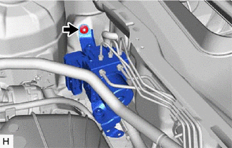
(j) Remove the nut and brake actuator with bracket. NOTICE:
HINT: Remove the brake actuator with bracket while avoiding the brake lines. |
|
8. REMOVE BRAKE ACTUATOR ASSEMBLY
|
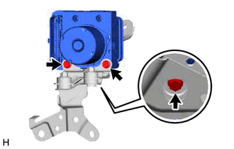
(a) Remove the 3 bolts and brake actuator assembly from the brake actuator bracket assembly. NOTICE:
|
|
9. REMOVE NO. 2 BRAKE ACTUATOR CASE COLLAR
|
(a) Remove the 3 nuts. |
|
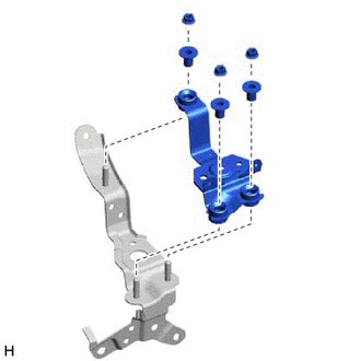
(b) Remove the 3 No. 2 brake actuator case collars from the brake actuator bracket cushion.
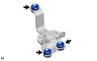
10. REMOVE BRAKE ACTUATOR BRACKET CUSHION
|
(a) Remove the 3 brake actuator bracket cushions from the brake actuator bracket assembly. |
|
|
|
|