| Last Modified: 09-10-2025 | 6.11:8.1.0 | Doc ID: RM100000001XOF8 |
| Model Year Start: 2022 | Model: Avalon HV | Prod Date Range: [08/2021 - ] |
| Title: PARKING BRAKE: ELECTRIC PARKING BRAKE SYSTEM (for HV Model): C123A14; IG1 Circuit Short to Ground or Open; 2022 MY Avalon HV [08/2021 - ] | ||
|
DTC |
C123A14 |
IG1 Circuit Short to Ground or Open |
DESCRIPTION
|
DTC No. |
Detection Item |
DTC Detection Condition |
Trouble Area |
Memory |
Note |
|---|---|---|---|---|---|
|
C123A14 |
IG1 Circuit Short to Ground or Open |
Both of following conditions are met:
|
|
DTC stored |
An electric parking brake system malfunction is displayed on the combination meter assembly. |
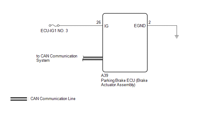
WIRING DIAGRAM
CAUTION / NOTICE / HINT
NOTICE:
Inspect the fuses for circuits related to this system before performing the following procedure.
PROCEDURE
PROCEDURE
|
1. |
READ VALUE USING TECHSTREAM (IG1 VOLTAGE) |
(a) Read the Data List according to the display on the Techstream.
Chassis > Electric Parking Brake > Data List
|
Tester Display |
Measurement Item |
Range |
Normal Condition |
Diagnostic Note |
|---|---|---|---|---|
|
IG1 Voltage |
IG voltage value |
Min.: 0.0 V Max.: 25.5 V |
Power switch on (IG): 11.0 to 14.0 V |
Changes in proportion to auxiliary battery voltage |
Chassis > Electric Parking Brake > Data List
|
Tester Display |
|---|
|
IG1 Voltage |
|
Result |
Proceed to |
|---|---|
|
The value of IG1 Voltage is between 11 and 14 V |
A |
|
None of the above conditions are met |
B |
| B |

|
|

|
2. |
CLEAR DTC |
(a) Clear the DTCs.
Chassis > Electric Parking Brake > Clear DTCs
(b) Turn the Power switch off.
|
|
3. |
CHECK DTC |
(a) Check for DTCs.
Chassis > Electric Parking Brake > Trouble Codes
|
Result |
Proceed to |
|---|---|
|
C123A14 is output |
A |
|
C123A14 is not output |
B |
| A |
|
| B |
|
|
4. |
CHECK HARNESS AND CONNECTOR (IG TERMINAL VOLTAGE) |
(a) Turn the Power switch off.
(b) Make sure that there is no looseness at the locking part and the connecting part of the connectors.
OK:
The connector is securely connected.
(c) Disconnect the A39 parking brake ECU (brake actuator assembly) connector.
(d) Check both the connector case and the terminals for deformation and corrosion.
OK:
No deformation or corrosion.
(e) Turn the power switch on (IG).
(f) Measure the voltage according to the value(s) in the table below.
Standard Voltage:
|
Tester Connection |
Condition |
Specified Condition |
|---|---|---|
|
A39-26 (IG) - Body ground |
Power switch on (IG) |
11 to 14 V |
| NG |
|
REPAIR OR REPLACE HARNESS OR CONNECTOR |
|
|
5. |
CHECK HARNESS AND CONNECTOR (EGND TERMINAL) |
(a) Turn the Power switch off.
(b) Disconnect the A39 parking brake ECU (brake actuator assembly) connector.
(c) Measure the resistance according to the value(s) in the table below.
Standard Resistance:
|
Tester Connection |
Condition |
Specified Condition |
|---|---|---|
|
A39-2 (EGND) - Body ground |
Always |
Below 1 Ω |
| OK |
|
| NG |
|
REPAIR OR REPLACE HARNESS OR CONNECTOR |
|
|
|