| Last Modified: 09-10-2025 | 6.11:8.1.0 | Doc ID: RM100000001XNMX |
| Model Year Start: 2022 | Model: Avalon | Prod Date Range: [08/2021 - ] |
| Title: BRAKE CONTROL / DYNAMIC CONTROL SYSTEMS: ELECTRONICALLY CONTROLLED BRAKE SYSTEM (for Gasoline Model): C051214; Right Rear Wheel Speed Sensor Circuit Short to Ground or Open; 2022 MY Avalon [08/2021 - ] | ||
|
DTC |
C051214 |
Right Rear Wheel Speed Sensor Circuit Short to Ground or Open |
DESCRIPTION
Refer to DTC C051212
Click here
![2022 MY Avalon [08/2021 - ]; BRAKE CONTROL / DYNAMIC CONTROL SYSTEMS: ELECTRONICALLY CONTROLLED BRAKE SYSTEM (for Gasoline Model): C051212; Right Rear Wheel Speed Sensor Circuit Short to Battery](/t3Portal/stylegraphics/info.gif)
|
DTC No. |
Detection Item |
DTC Detection Condition |
Trouble Area |
|---|---|---|---|
|
C051214 |
Right Rear Wheel Speed Sensor Circuit Short to Ground or Open |
A short or open circuit is detected in the speed sensor signal circuit for 0.12 seconds or more. |
|
- *1: for 2WD
- *2: for AWD
DTC Detection Conditions: C051214
|
Vehicle Condition |
|||
|---|---|---|---|
|
Pattern 1 |
Pattern 2 |
||
|
Diagnosis Condition |
- |
- |
- |
|
Malfunction Status |
An open circuit is detected in the speed sensor signal circuit. |
○ |
- |
|
A short circuit is detected in the speed sensor signal circuit. |
- |
○ |
|
|
Detection Time |
0.12 seconds or more. |
0.12 seconds or more. |
|
|
Number of Trips |
1 trip |
1 trip |
|
HINT:
DTC will be output when conditions for either of the patterns in the table above are met.
WIRING DIAGRAM
Refer to DTC C051212.
Click here
CAUTION / NOTICE / HINT
NOTICE:
-
After replacing the skid control ECU (brake actuator assembly), perform acceleration sensor zero point calibration and system information memorization.
Click here
-
After replacing or removing and installing a speed sensor, perform Dealer Mode (Signal Check) inspection to confirm that the speed sensors are operating correctly.
Click here
PROCEDURE
PROCEDURE
|
1. |
CHECK VEHICLE |
(a) Check the vehicle specification.
|
Result |
Proceed to |
|---|---|
|
for 2WD |
A |
|
for AWD |
B |
| B |

|
|

|
2. |
CHECK HARNESS AND CONNECTOR (SENSOR GROUND CIRCUIT) |
|
(a) Make sure that there is no looseness at the locking part and the connecting part of the connectors. OK: The connector is securely connected. |
|
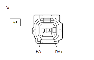
(b) Disconnect the Y5 rear speed sensor RH (rear axle hub and bearing assembly RH) connector.
(c) Check both the connector case and the terminals for deformation and corrosion.
OK:
No deformation or corrosion.
(d) Turn the engine switch on (IG).
(e) Measure the voltage according to the value(s) in the table below.
Standard Voltage:
|
Tester Connection |
Condition |
Specified Condition |
|---|---|---|
|
Y5-2 (RA+) - Y5-1 (RA-) |
Engine switch on (IG) |
11 to 14 V |
|
Result |
Proceed to |
|---|---|
|
OK (w/o AVS) |
A |
|
OK (w/ AVS) |
B |
|
NG (w/o AVS) |
C |
|
NG (w/ AVS) |
D |
| B |
|
| C |
|
| D |
|
|
|
3. |
INSPECT NO. 1 PARKING BRAKE WIRE ASSEMBLY |
|
(a) Make sure that there is no looseness at the locking part and the connecting part of the connectors. OK: The connector is securely connected. |
|
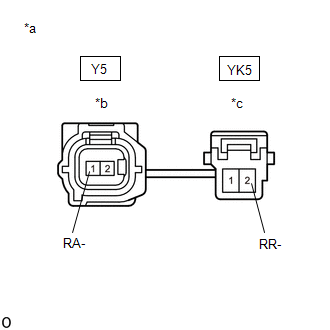
(b) Disconnect the Y5 skid control sensor wire RH (No. 1 parking brake wire assembly) connector.
(c) Disconnect the YK5 skid control sensor wire RH (No. 1 parking brake wire assembly) connector.
(d) Check both the connector case and the terminals for deformation and corrosion.
OK:
No deformation or corrosion.
(e) Measure the resistance according to the value(s) in the table below.
Standard Resistance:
|
Tester Connection |
Condition |
Specified Condition |
|---|---|---|
|
Y5-1 (RA-) or YK5-2 (RR-) - Body ground and other terminals |
Always |
10 kΩ or higher |
| NG |
|
REPLACE NO. 1 PARKING BRAKE WIRE ASSEMBLY |
|
|
4. |
CHECK HARNESS AND CONNECTOR (NO. 1 PARKING BRAKE WIRE ASSEMBLY - BRAKE ACTUATOR ASSEMBLY) |
(a) Make sure that there is no looseness at the locking part and the connecting part of the connectors.
OK:
The connector is securely connected.
(b) Disconnect the A28 skid control ECU (brake actuator assembly) connector.
(c) Disconnect the YK5 skid control sensor wire RH (No. 1 parking brake wire assembly) connector.
(d) Check both the connector case and the terminals for deformation and corrosion.
OK:
No deformation or corrosion.
(e) Measure the resistance according to the value(s) in the table below.
Standard Resistance:
|
Tester Connection |
Condition |
Specified Condition |
|---|---|---|
|
YK5-2 (RR-) or A28-37 (RR-) - Body ground |
Always |
10 kΩ or higher |
| OK |
|
| NG |
|
REPAIR OR REPLACE HARNESS OR CONNECTOR |
|
5. |
INSPECT NO. 1 PARKING BRAKE WIRE ASSEMBLY |
|
(a) Make sure that there is no looseness at the locking part and the connecting part of the connectors. OK: The connector is securely connected. |
|
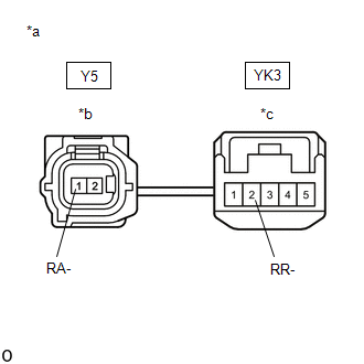
(b) Disconnect the Y5 skid control sensor wire RH (No. 1 parking brake wire assembly) connector.
(c) Disconnect the YK3 skid control sensor wire RH (No. 1 parking brake wire assembly) connector.
(d) Check both the connector case and the terminals for deformation and corrosion.
OK:
No deformation or corrosion.
(e) Measure the resistance according to the value(s) in the table below.
Standard Resistance:
|
Tester Connection |
Condition |
Specified Condition |
|---|---|---|
|
Y5-1 (RA-) or YK3-2 (RR-) - Body ground and other terminals |
Always |
10 kΩ or higher |
| NG |
|
REPLACE NO. 1 PARKING BRAKE WIRE ASSEMBLY |
|
|
6. |
CHECK HARNESS AND CONNECTOR (NO. 1 PARKING BRAKE WIRE ASSEMBLY - BRAKE ACTUATOR ASSEMBLY) |
(a) Make sure that there is no looseness at the locking part and the connecting part of the connectors.
OK:
The connector is securely connected.
(b) Disconnect the A28 skid control ECU (brake actuator assembly) connector.
(c) Disconnect the YK3 skid control sensor wire RH (No. 1 parking brake wire assembly) connector.
(d) Check both the connector case and the terminals for deformation and corrosion.
OK:
No deformation or corrosion.
(e) Measure the resistance according to the value(s) in the table below.
Standard Resistance:
|
Tester Connection |
Condition |
Specified Condition |
|---|---|---|
|
YK3-2 (RR-) or A28-37 (RR-) - Body ground |
Always |
10 kΩ or higher |
| OK |
|
| NG |
|
REPAIR OR REPLACE HARNESS OR CONNECTOR |
|
7. |
INSPECT NO. 1 PARKING BRAKE WIRE ASSEMBLY |
|
(a) Make sure that there is no looseness at the locking part and the connecting part of the connectors. OK: The connector is securely connected. |
|
(b) Disconnect the Y5 skid control sensor wire RH (No. 1 parking brake wire assembly) connector.
(c) Disconnect the YK5 skid control sensor wire RH (No. 1 parking brake wire assembly) connector.
(d) Check both the connector case and the terminals for deformation and corrosion.
OK:
No deformation or corrosion.
(e) Measure the resistance according to the value(s) in the table below.
Standard Resistance:
|
Tester Connection |
Condition |
Specified Condition |
|---|---|---|
|
Y5-1 (RA-) - YK5-2 (RR-) |
Always |
Below 1 Ω |
| NG |
|
REPLACE NO. 1 PARKING BRAKE WIRE ASSEMBLY |
|
|
8. |
CHECK HARNESS AND CONNECTOR (NO. 1 PARKING BRAKE WIRE ASSEMBLY - BRAKE ACTUATOR ASSEMBLY) |
(a) Make sure that there is no looseness at the locking part and the connecting part of the connectors.
OK:
The connector is securely connected.
(b) Disconnect the A28 skid control ECU (brake actuator assembly) connector.
(c) Disconnect the YK5 skid control sensor wire RH (No. 1 parking brake wire assembly) connector.
(d) Check both the connector case and the terminals for deformation and corrosion.
OK:
No deformation or corrosion.
(e) Measure the resistance according to the value(s) in the table below.
Standard Resistance:
|
Tester Connection |
Condition |
Specified Condition |
|---|---|---|
|
YK5-2 (RR-) - A28-37 (RR-) |
Always |
Below 1 Ω |
| OK |
|
| NG |
|
REPAIR OR REPLACE HARNESS OR CONNECTOR |
|
9. |
INSPECT NO. 1 PARKING BRAKE WIRE ASSEMBLY |
|
(a) Make sure that there is no looseness at the locking part and the connecting part of the connectors. OK: The connector is securely connected. |
|
(b) Disconnect the Y5 skid control sensor wire RH (No. 1 parking brake wire assembly) connector.
(c) Disconnect the YK3 skid control sensor wire RH (No. 1 parking brake wire assembly) connector.
(d) Check both the connector case and the terminals for deformation and corrosion.
OK:
No deformation or corrosion.
(e) Measure the resistance according to the value(s) in the table below.
Standard Resistance:
|
Tester Connection |
Condition |
Specified Condition |
|---|---|---|
|
Y5-1 (RA-) - YK3-2 (RR-) |
Always |
Below 1 Ω |
| NG |
|
REPLACE NO. 1 PARKING BRAKE WIRE ASSEMBLY |
|
|
10. |
CHECK HARNESS AND CONNECTOR (NO. 1 PARKING BRAKE WIRE ASSEMBLY - BRAKE ACTUATOR ASSEMBLY) |
(a) Make sure that there is no looseness at the locking part and the connecting part of the connectors.
OK:
The connector is securely connected.
(b) Disconnect the A28 skid control ECU (brake actuator assembly) connector.
(c) Disconnect the YK3 skid control sensor wire RH (No. 1 parking brake wire assembly) connector.
(d) Check both the connector case and the terminals for deformation and corrosion.
OK:
No deformation or corrosion.
(e) Measure the resistance according to the value(s) in the table below.
Standard Resistance:
|
Tester Connection |
Condition |
Specified Condition |
|---|---|---|
|
YK3-2 (RR-) - A28-37 (RR-) |
Always |
Below 1 Ω |
| OK |
|
| NG |
|
REPAIR OR REPLACE HARNESS OR CONNECTOR |
|
11. |
CHECK HARNESS AND CONNECTOR (SENSOR GROUND CIRCUIT) |
|
(a) Make sure that there is no looseness at the locking part and the connecting part of the connectors. OK: The connector is securely connected. |
|
(b) Disconnect the Y5 rear speed sensor RH connector.
(c) Check both the connector case and the terminals for deformation and corrosion.
OK:
No deformation or corrosion.
(d) Turn the engine switch to on (IG).
(e) Measure the voltage according to the value(s) in the table below.
Standard Voltage:
|
Tester Connection |
Condition |
Specified Condition |
|---|---|---|
|
Y5-2 (RA+) - Y5-1 (RA-) |
Engine switch on (IG) |
11 to 14 V |
| NG |
|
|
|
12. |
INSPECT NO. 1 PARKING BRAKE WIRE ASSEMBLY |
|
(a) Make sure that there is no looseness at the locking part and the connecting part of the connectors. OK: The connector is securely connected. |
|
(b) Disconnect the Y5 skid control sensor wire RH (No. 1 parking brake wire assembly) connector.
(c) Disconnect the YK5 skid control sensor wire RH (No. 1 parking brake wire assembly) connector.
(d) Check both the connector case and the terminals for deformation and corrosion.
OK:
No deformation or corrosion.
(e) Measure the resistance according to the value(s) in the table below.
Standard Resistance:
|
Tester Connection |
Condition |
Specified Condition |
|---|---|---|
|
Y5-1 (RA-) or YK5-2 (RR-) - Body ground and other terminals |
Always |
10 kΩ or higher |
| NG |
|
REPLACE NO. 1 PARKING BRAKE WIRE ASSEMBLY |
|
|
13. |
CHECK HARNESS AND CONNECTOR (NO. 1 PARKING BRAKE WIRE ASSEMBLY - BRAKE ACTUATOR ASSEMBLY) |
(a) Make sure that there is no looseness at the locking part and the connecting part of the connectors.
OK:
The connector is securely connected.
(b) Disconnect the A28 skid control ECU (brake actuator assembly) connector.
(c) Disconnect the YK5 skid control sensor wire RH (No. 1 parking brake wire assembly) connector.
(d) Check both the connector case and the terminals for deformation and corrosion.
OK:
No deformation or corrosion.
(e) Measure the resistance according to the value(s) in the table below.
Standard Resistance:
|
Tester Connection |
Condition |
Specified Condition |
|---|---|---|
|
YK5-2 (RR-) or A28-37 (RR-) - Body ground |
Always |
10 kΩ or higher |
| OK |
|
| NG |
|
REPAIR OR REPLACE HARNESS OR CONNECTOR |
|
|
|