| 
                     
                        | Last Modified: 08-21-2023 | 6.11:8.1.0 | Doc ID: RM100000001RUPG |  
                        | Model Year Start: 2021 | Model: Avalon | Prod Date Range: [08/2020 -                    
                                       ] |  
                        | Title: NAVIGATION / MULTI INFO DISPLAY: NAVIGATION SYSTEM (for Gasoline Model): Mute Signal Circuit between Stereo Component Amplifier and Telematics Transceiver; 2021 - 2022 MY Avalon [08/2020 -        ] |  
                     
                        
                           | Mute Signal Circuit between Stereo Component Amplifier and Telematics Transceiver |  DESCRIPTIONThe DCM (telematics transceiver) sends a mute signal to the stereo component amplifier assembly. The stereo component amplifier assembly controls the volume according to the mute signal from the DCM (telematics transceiver).
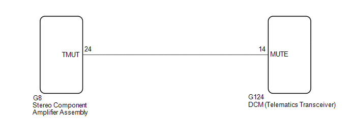
 WIRING DIAGRAM  CAUTION / NOTICE / HINT
                     NOTICE: 
                        
Depending on the parts that are replaced during vehicle inspection or maintenance, performing initialization, registration or calibration may be needed. Refer to Precaution for Navigation System.
Click here
                                 
                                    
                                       ![2019 - 2021 MY Avalon [04/2018 - 08/2021]; NAVIGATION / MULTI INFO DISPLAY: NAVIGATION SYSTEM (for Gasoline Model): PRECAUTION](/t3Portal/stylegraphics/info.gif)  ![2022 MY Avalon [08/2021 -        ]; NAVIGATION / MULTI INFO DISPLAY: NAVIGATION SYSTEM (for Gasoline Model): PRECAUTION](/t3Portal/stylegraphics/info.gif) 
Before replacing the DCM (telematics transceiver), refer to Registration.
Click here
                                 
                                    
                                       ![2021 - 2022 MY Avalon [08/2020 -        ]; THEFT DETERRENT / KEYLESS ENTRY: SMART KEY SYSTEM (for Start Function, Gasoline Model): REGISTRATION](/t3Portal/stylegraphics/info.gif)  PROCEDURE
                     
                        
                           | 1.  | INSPECT DCM (TELEMATICS TRANSCEIVER) |  
                     
                        
                           | (a) Measure the voltage according to the value(s) in the table below. Standard Voltage:  


                                       | Tester Connection | Condition | Specified Condition |  
                                       | G124-14 (MUTE) - Body ground | Engine switch on (ACC) Audio system playing → Emergency call mode | 2.0 V or higher → Below 1 V |  | 
                                 
                                    |   |  
                                    | 


                                                | *a | Component with harness connected (DCM (Telematics Transceiver)) |  |  |  
                     
                        | 
                              
                                 | NG |  
                                 |   |  |  
                     
                        
                           | 2.  | CHECK HARNESS AND CONNECTOR (STEREO COMPONENT AMPLIFIER ASSEMBLY - DCM (TELEMATICS TRANSCEIVER)) |  (a) Disconnect the G8 stereo component amplifier assembly connector. 
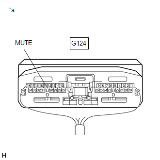
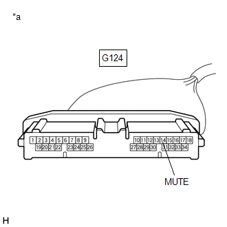
(b) Disconnect the G124 DCM (telematics transceiver) connector. (c) Measure the resistance according to the value(s) in the table below. Standard Resistance:  


                           | Tester Connection | Condition | Specified Condition |  
                           | G8-24 (TMUT) - G124-14 (MUTE) | Always | Below 1 Ω |  
                           | G8-24 (TMUT) or G124-14 (MUTE) - Body ground | Always | 10 kΩ or higher |  
                     
                        
                           | NG |   | REPAIR OR REPLACE HARNESS OR CONNECTOR |  
                     
                        | 
                              
                                 | OK |  
                                 |   |  |  
                     
                        
                           | 3.  | INSPECT STEREO COMPONENT AMPLIFIER ASSEMBLY |  (a) Disconnect the G124 DCM (telematics transceiver) connector. 
                     
                        
                           | (b) Measure the voltage according to the value(s) in the table below. Standard Voltage:  


                                       | Tester Connection | Condition | Specified Condition |  
                                       | G124-14 (MUTE) - Body ground | Engine switch on (ACC) | 2.0 V or higher |  | 
                                 
                                    |   |  
                                    | 


                                                | *a | Front view of wire harness connector (to DCM (Telematics Transceiver)) |  |  |  |