| 
                     
                        | Last Modified: 08-21-2023 | 6.11:8.1.0 | Doc ID: RM100000001RUPD |  
                        | Model Year Start: 2021 | Model: Avalon | Prod Date Range: [08/2020 -                    
                                       ] |  
                        | Title: NAVIGATION / MULTI INFO DISPLAY: NAVIGATION SYSTEM (for Gasoline Model): Data Signal Circuit between Radio Receiver and Stereo Jack Adapter; 2021 - 2022 MY Avalon [08/2020 -        ] |  
                     
                        
                           | Data Signal Circuit between Radio Receiver and Stereo Jack Adapter |  DESCRIPTION
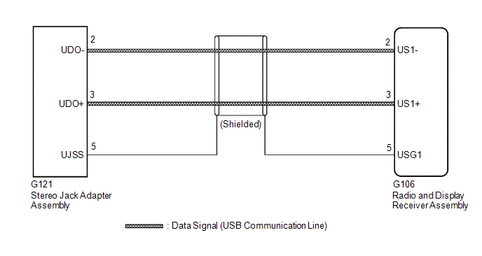
The stereo jack adapter assembly sends the sound data signal or image data signal from a USB device to the radio and display receiver assembly via this circuit. WIRING DIAGRAM  PROCEDURE
                     
                        
                           | 1.  | CHECK HARNESS AND CONNECTOR (RADIO AND DISPLAY RECEIVER ASSEMBLY - STEREO JACK ADAPTER ASSEMBLY) |  
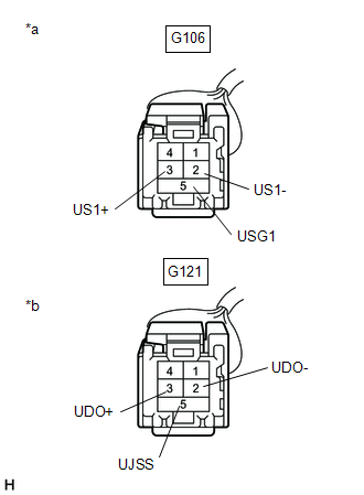
(a) Disconnect the G106 radio and display receiver assembly connector. (b) Disconnect the G121 stereo jack adapter assembly connector. 
                     
                        
                           | (c) Measure the resistance according to the value(s) in the table below. Standard Resistance:  


                                       | Tester Connection | Condition | Specified Condition |  
                                       | G106-2 (US1-) - G121-2 (UDO-) | Always | Below 1 Ω |  
                                       | G106-3 (US1+) - G121-3 (UDO+) | Always | Below 1 Ω |  
                                       | G106-5 (USG1) - G121-5 (UJSS) | Always | Below 1 Ω |  
                                       | G106-2 (US1-) or G121-2 (UDO-) - Body ground | Always | 10 kΩ or higher |  
                                       | G106-3 (US1+) or G121-3 (UDO+) - Body ground | Always | 10 kΩ or higher |  
                                       | G106-5 (USG1) or G121-5 (UJSS) - Body ground | Always | 10 kΩ or higher |  | 
                                 
                                    |   |  
                                    | 


                                                | *a | Front view of wire harness connector (to Radio and Display Receiver Assembly) |  
                                                | *b | Front view of wire harness connector (to Stereo Jack Adapter Assembly) |  |  |  
                     
                        
                           | NG |   | REPAIR OR REPLACE HARNESS OR CONNECTOR |  |