
- Engine running
- Blower switch: LO
- A/C switch: On
| Last Modified: 09-10-2025 | 6.11:8.1.0 | Doc ID: RM100000001RUIH |
| Model Year Start: 2021 | Model: Avalon | Prod Date Range: [08/2020 - ] |
| Title: HEATING / AIR CONDITIONING: AIR CONDITIONING SYSTEM (for Gasoline Model): B1451; Compressor Solenoid Circuit; 2021 - 2022 MY Avalon [08/2020 - ] | ||
|
DTC |
B1451 |
Compressor Solenoid Circuit |
DESCRIPTION
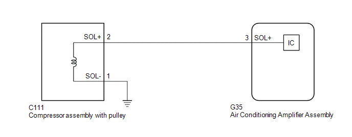
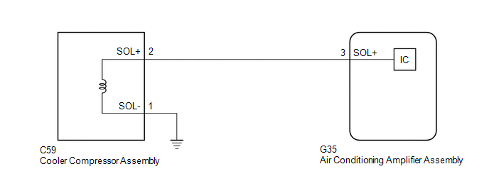
The compressor assembly with pulley*1 or cooler compressor assembly*2 receives refrigerant compression demand signals from the air conditioning amplifier assembly.
Based on this signal, the compressor assembly with pulley*1 or cooler compressor assembly*2 changes the amount of compressor output.
|
DTC No. |
Detection Item |
DTC Detection Condition |
Trouble Area |
Memory |
|---|---|---|---|---|
|
B1451 |
Compressor Solenoid Circuit |
Open or short in compressor solenoid circuit |
|
- |
- *1: for A25A-FKS
- *2: for 2GR-FKS
WIRING DIAGRAM
for A25A-FKS:
for 2GR-FKS:
PROCEDURE
PROCEDURE
|
1. |
CONFIRM MODEL |
|
Result |
Proceed to |
|---|---|
|
for A25A-FKS |
A |
|
for 2GR-FKS |
B |
| B |

|
|
|
2. |
INSPECT AIR CONDITIONING AMPLIFIER ASSEMBLY |
|
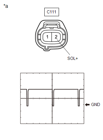
*a |
Front view of wire harness connector (to Compressor Assembly with Pulley) |
(a) Disconnect the C111 compressor assembly with pulley connector.
(b) Connect an oscilloscope to terminal C111-2 (SOL+) and body ground and check the waveform.
|
Item |
Content |
|---|---|
|
Tool Setting |
5 V/DIV., 500 μs./DIV. |
|
Condition |
|
OK:
Waveform is similar to that shown in the illustration.
| OK |
|
REPLACE COMPRESSOR ASSEMBLY WITH PULLEY Click here
|
![2019 - 2021 MY Avalon HV [04/2018 - 08/2021]; HEATING / AIR CONDITIONING: COMPRESSOR (for A25A-FXS): REMOVAL](/t3Portal/stylegraphics/info.gif)
| NG |
|
|
3. |
CHECK HARNESS AND CONNECTOR (COMPRESSOR ASSEMBLY WITH PULLEY - AIR CONDITIONING AMPLIFIER ASSEMBLY) |
(a) Disconnect the G35 air conditioning amplifier assembly connector.
(b) Measure the resistance according to the value(s) in the table below.
Standard Resistance:
|
Tester Connection |
Condition |
Specified Condition |
|---|---|---|
|
C111-2 (SOL+) - G35-3 (SOL+) |
Always |
Below 1 Ω |
|
C111-2 (SOL+) or G35-3 (SOL+) - Other terminals and body ground |
Always |
10 kΩ or higher |
| OK |
|
| NG |
|
REPAIR OR REPLACE HARNESS OR CONNECTOR |
|
4. |
INSPECT AIR CONDITIONING AMPLIFIER ASSEMBLY |
|
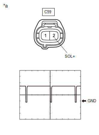
*a |
Front view of wire harness connector (to Cooler Compressor Assembly) |
(a) Disconnect the C59 cooler compressor assembly connector.
(b) Connect an oscilloscope to terminal C59-2 (SOL+) and body ground and check the waveform.
|
Item |
Content |
|---|---|
|
Tool Setting |
5 V/DIV., 500 μs./DIV. |
|
Condition |
|
OK:
Waveform is similar to that shown in the illustration.
| OK |
|
| NG |
|
|
5. |
CHECK HARNESS AND CONNECTOR (COOLER COMPRESSOR ASSEMBLY - AIR CONDITIONING AMPLIFIER ASSEMBLY) |
(a) Disconnect the G35 air conditioning amplifier assembly connector.
(b) Measure the resistance according to the value(s) in the table below.
Standard Resistance:
|
Tester Connection |
Condition |
Specified Condition |
|---|---|---|
|
C59-2 (SOL+) - G35-3 (SOL+) |
Always |
Below 1 Ω |
|
C59-2 (SOL+) or G35-3 (SOL+) - Other terminals and body ground |
Always |
10 kΩ or higher |
| OK |
|
| NG |
|
REPAIR OR REPLACE HARNESS OR CONNECTOR |
|
|
|