| Last Modified: 08-21-2023 | 6.11:8.1.0 | Doc ID: RM100000001RM9G |
| Model Year Start: 2021 | Model: Avalon HV | Prod Date Range: [08/2020 - ] |
| Title: HYBRID / BATTERY CONTROL: FRAME WIRE: INSTALLATION; 2021 - 2022 MY Avalon HV [08/2020 - ] | ||
INSTALLATION
PROCEDURE
1. INSTALL FLOOR UNDER WIRE
CAUTION:
Be sure to wear insulated gloves.
|
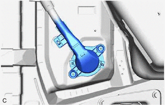
(a) Insert the HV floor under wire into the floor panel hole and engage the grommet. |
|
|
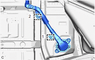
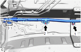
(b) Install 2 new clamps in the order shown in the illustration. |
|
|
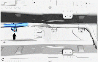
(c) Install the nut. Torque: 8.0 N·m {82 kgf·cm, 71 in·lbf} |
|
|
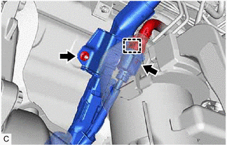
(d) Install the 2 nuts and new clamp in the order shown in the illustration. Torque: 8.0 N·m {82 kgf·cm, 71 in·lbf} |
|
|
(e) Install the nut. Torque: 8.0 N·m {82 kgf·cm, 71 in·lbf} |
|
(f) Connect the HV floor under wire connector.
(g) Engage the clamp.
|
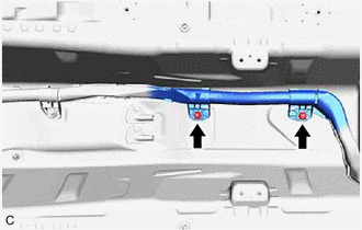
(h) Install the 2 nuts. Torque: 8.0 N·m {82 kgf·cm, 71 in·lbf} |
|
|
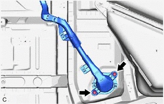
(i) Install the HV floor under wire with the 2 nuts. Torque: 8.0 N·m {82 kgf·cm, 71 in·lbf} |
|
2. CONNECT TRANSMISSION CONTROL CABLE ASSEMBLY
(a) Connect the transmission control cable assembly to the vehicle body with the 2 nuts.
Torque:
6.0 N·m {61 kgf·cm, 53 in·lbf}
3. INSTALL CENTER NO. 2 FLOOR HEAT INSULATOR
(a) Install the center No. 2 floor heat insulator with the 3 nuts.
Torque:
5.0 N·m {51 kgf·cm, 44 in·lbf}
4. INSTALL NO. 1 FLOOR UNDER COVER
5. INSTALL EXHAUST MANIFOLD
6. INSTALL FRONT EXHAUST PIPE ASSEMBLY
7. CONNECT FLOOR UNDER WIRE
CAUTION:
Be sure to wear insulated gloves.
(a) Connect the floor wire connector.
(b) Connect the shield ground to the HV battery.
(c) Connect the 2 HV battery junction block assembly connectors.
NOTICE:
Make sure that the connectors are connected securely.
8. INSTALL NO. 1 HV BATTERY COVER PANEL RH
9. INSTALL REAR SEAT CUSHION LEG SUB-ASSEMBLY
10. INSTALL REAR UNDER COVER
11. INSTALL REAR UNDER SIDE COVER LH
12. INSTALL REAR DOOR SCUFF PLATE LH
13. INSTALL REAR UNDER SIDE COVER RH
14. INSTALL REAR DOOR SCUFF PLATE RH
HINT:
Use the same procedure as for the LH side.
15. INSTALL REAR SEAT CUSHION LOCK HOOK
16. INSTALL REAR SEAT CUSHION ASSEMBLY
17. CONNECT REAR CENTER SEAT OUTER BELT ASSEMBLY
18. CONNECT FLOOR UNDER WIRE
19. CONNECT ENGINE ROOM MAIN WIRE
CAUTION:
Be sure to wear insulated gloves.
NOTICE:
Do not allow any foreign matter or water to enter the inverter with converter assembly.
|
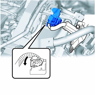
(a) Connect the inverter with converter assembly connector and move the lock lever to lock them. NOTICE:
|
|
20. INSTALL SERVICE PLUG GRIP
21. INSPECT FOR EXHAUST GAS LEAK
If gas is leaking, tighten the areas necessary to stop the leak. Replace damaged parts as necessary.
(a) Perform "Inspection After Repair" after repairing an exhaust gas leak.
|
|
|
![2021 - 2022 MY Avalon Avalon HV [08/2020 - ]; REAR SUSPENSION: REAR TRAILING ARM: INSTALLATION+](/t3Portal/stylegraphics/info.gif)
