| Last Modified: 08-21-2023 | 6.11:8.1.0 | Doc ID: RM100000001RHDD |
| Model Year Start: 2021 | Model: Avalon HV | Prod Date Range: [08/2020 - ] |
| Title: HYBRID / BATTERY CONTROL: HYBRID CONTROL SYSTEM (for LITHIUM-ION BATTERY): TERMINALS OF ECU; 2021 - 2022 MY Avalon HV [08/2020 - ] | ||
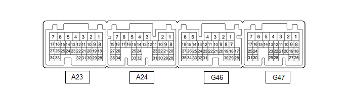
TERMINALS OF ECU
|
Terminal No. (Symbol) |
Wiring Color |
Terminal Description |
Input/Output |
Condition |
Specified Condition |
|---|---|---|---|---|---|
|
A23-1 (+B2) - G46-6 (E1) |
W - W-B |
Power source |
Input |
Power switch on (IG) |
11 to 14 V |
|
A23-3 (IG2) - G46-6 (E1) |
B - W-B |
Power source |
Input |
Power switch on (IG) |
11 to 14 V |
|
A23-8 (VCP2) - A23-18 (EPA2) |
SB - P |
Accelerator pedal sensor assembly power source (for VPA2) |
Output |
Power switch on (IG) |
4.5 to 5.5 V |
|
A23-9 (VCPA) - A23-20 (EPA) |
BE - L |
Accelerator pedal sensor assembly power source (for VPA) |
Output |
Power switch on (IG) |
4.5 to 5.5 V |
|
A23-13 (IWP) - G46-6 (E1) |
L - W-B |
Inverter water pump with motor assembly signal |
Output |
Power switch on (READY) |
Pulse generation (Waveform 1) |
|
A23-14 (NIWP) - G46-6 (E1) |
W - W-B |
Inverter water pump with motor assembly signal |
Input |
Power switch on (READY) |
Pulse generation (Waveform 1) |
|
A23-15 (STP) - G46-6 (E1) |
LA-G - W-B |
Stop light switch |
Input |
Brake pedal depressed |
11 to 14 V |
|
Brake pedal released |
0 to 1.5 V |
||||
|
A23-17 (LIN3) - G46-6 (E1) |
L - W-B |
LIN communication signal (A/C inverter, auxiliary battery state sensor) |
Input/Output |
Power switch on (READY) |
Pulse generation |
|
A23-21 (TTA) - A23-31 (ETTA) |
GR - SB |
Transmission fluid temperature sensor |
Input |
Power switch on (IG), temperature 25°C (77°F) |
3.6 to 4.6 V |
|
Power switch on (IG), temperature 60°C (140°F) |
2.2 to 3.2 V |
||||
|
A23-22 (ACCI) - G46-6 (E1) |
P - W-B |
ACC relay |
Input |
Power switch on (ACC) |
11 to 14 V |
|
A23-24 (MMT) - A23-23 (MMTG) |
G - R |
Motor temperature sensor |
Input |
Power switch on (IG), temperature 25°C (77°F) |
3.6 to 4.6 V |
|
Power switch on (IG), temperature 60°C (140°F) |
2.2 to 3.2 V |
||||
|
A23-26 (GMT) - A23-27 (GMTG) |
P - V |
Generator temperature sensor |
Input |
Power switch on (IG), temperature 25°C (77°F) |
3.6 to 4.6 V |
|
Power switch on (IG), temperature 60°C (140°F) |
2.2 to 3.2 V |
||||
|
A23-28 (VPA2) - A23-18 (EPA2) |
GR - P |
Accelerator pedal sensor assembly (for accelerator pedal position detection) |
Input |
Power switch on (IG), accelerator pedal released |
1.0 to 2.2 V |
|
Power switch on (IG), engine stopped, shift lever in P, accelerator pedal fully depressed |
3.4 to 5.3 V |
||||
|
A23-30 (VPA) - A23-20 (EPA) |
G - L |
Accelerator pedal sensor assembly (for accelerator pedal position detection) |
Input |
Power switch on (IG), accelerator pedal released |
0.4 to 1.4 V |
|
Power switch on (IG), engine stopped, shift lever in P, accelerator pedal fully depressed |
2.6 to 4.5 V |
||||
|
A24-1 (PSFT) - G46-6 (E1) |
L - W-B |
Shift lever position sensor power source |
Output |
Power switch on (ACC) |
6.0 to 14 V |
|
A24-2 (BL) - G46-6 (E1) |
BE - W-B |
Back-up light |
Output |
Power switch on (IG), shift lever in R |
11 to 14 V |
|
A24-4 (+B1) - G46-6 (E1) |
R - W-B |
Power source |
Input |
Power switch on (IG) |
11 to 14 V |
|
A24-6 (MREL) - G46-6 (E1) |
G - W-B |
Main relay |
Output |
Power switch on (IG) |
11 to 14 V |
|
A24-7 (IGB) - G46-6 (E1) |
B - W-B |
Power source |
Input |
Power switch on (IG) |
8.5 to 14 V |
|
A24-12 (HSDN) - G46-6 (E1) |
W - W-B |
MG ECU shutdown signal |
Output |
Power switch on (READY) |
0 to 1.5 V |
|
A24-13 (ILK) - G46-6 (E1) |
GR - W-B |
Interlock switch |
Input |
Power switch on (IG), service plug grip installed correctly |
0 to 1.5 V |
|
Power switch on (IG), service plug grip not installed |
11 to 14 V |
||||
|
A24-14 (DB2) - G46-6 (E1) |
V - W-B |
Shift lever position signal |
Input |
Power switch on (IG), shift lever in D or S |
6.0 to 14 V |
|
Power switch on (IG), shift lever not in D or S |
0 to 1.5 V |
||||
|
A24-15 (R) - G46-6 (E1) |
LG - W-B |
Shift lever position signal |
Input |
Power switch on (IG), shift lever in R |
6.0 to 14 V |
|
Power switch on (IG), shift lever not in R |
0 to 1.5 V |
||||
|
A24-17 (PR) - G46-6 (E1) |
R - W-B |
Shift lever position signal |
Input |
Power switch on (IG), shift lever in P or R |
6.0 to 14 V |
|
Power switch on (IG), shift lever not in P or R |
0 to 1.5 V |
||||
|
A24-20 (N) - G46-6 (E1) |
G - W-B |
Shift lever position signal |
Input |
Power switch on (IG), shift lever in N |
6.0 to 14 V |
|
Power switch on (IG), shift lever not in N |
0 to 1.5 V |
||||
|
A24-21 (P) - G46-6 (E1) |
BE - W-B |
Shift lever position signal |
Input |
Power switch on (IG), shift lever in P |
6.0 to 14 V |
|
Power switch on (IG), shift lever not in P |
0 to 1.5 V |
||||
|
A24-26 (DB1) - G46-6 (E1) |
W - W-B |
Shift lever position signal |
Input |
Power switch on (IG), shift lever in D or S |
6.0 to 14 V |
|
Power switch on (IG), shift lever not in D or S |
0 to 1.5 V |
||||
|
A24-28 (ST1-) - G46-6 (E1) |
LG - W-B |
Stop light switch signal |
Input |
Power switch on (IG), brake pedal depressed |
0 to 1.5 V |
|
Power switch on (IG), brake pedal released |
11 to 14 V |
||||
|
A24-30 (HMCL) - G46-6 (E1) |
W - W-B |
MG ECU communication request signal |
Input/Output |
Power switch on (IG) |
Pulse generation (Waveform 2) |
|
A24-31 (HMCH) - G46-6 (E1) |
B - W-B |
MG ECU communication request signal |
Input/Output |
Power switch on (IG) |
Pulse generation (Waveform 2) |
|
A24-34 (PNB) - G46-6 (E1) |
B - W-B |
Shift lever position signal |
Input |
Power switch on (IG), shift lever in P or N |
6.0 to 14 V |
|
G46-1 (SMRG) - G46-5 (E01) |
G - W-B |
System main relay operation signal |
Output |
Power switch on (IG) → Power switch on (READY) |
Pulse generation (Waveform 3) |
|
G46-3 (SMRP) - G46-5 (E01) |
W - W-B |
System main relay operation signal |
Output |
Power switch on (IG) → Power switch on (READY) |
Pulse generation (Waveform 3) |
|
G46-4 (SMRB) - G46-5 (E01) |
GR - W-B |
System main relay operation signal |
Output |
Power switch on (IG) → Power switch on (READY) |
Pulse generation (Waveform 3) |
|
G46-8 (INDR) - G46-6 (E1) |
LG - W-B |
Shift position indicator signal |
Input |
Power switch on (IG), shift lever in R |
0 to 3.2 V |
|
Power switch on (IG), shift lever not in R |
11 to 14 V |
||||
|
G46-9 (ST2) - G46-6 (E1) |
L - W-B |
Starter signal |
Input |
Power switch on (IG) |
0 to 1.5 V |
|
G46-10 (NORM) - G46-6(E1) |
LG - W-B |
Normal mode switch (electric parking brake switch assembly) signal |
Input |
Power switch on (IG), normal mode switch (electric parking brake switch assembly) not operated |
11 to 14 V |
|
Power switch on (IG), normal mode switch (electric parking brake switch assembly) operated |
0 to 1.5 V |
||||
|
G46-34 (CA4H) - G46-6 (E1) |
GR - W-B |
CAN communication signal |
Input/Output |
Power switch on (IG) |
Pulse generation (Waveform 4) |
|
G46-35 (CA4L) - G46-6 (E1) |
W - W-B |
CAN communication signal |
Input/Output |
Power switch on (IG) |
Pulse generation (Waveform 4) |
|
G47-1 (M) - G46-6 (E1) |
B - W-B |
Transmission control |
Input |
Power switch on (IG), shift lever in S |
11 to 14 V |
|
Power switch on (IG), shift lever not in S |
0 to 1.5 V |
||||
|
G47-3 (BATT) - G46-6 (E1) |
B - W-B |
Constant power source |
Input |
Power switch on (IG) |
11 to 14 V |
|
Power switch on (READY) |
11 to 15.5 V |
||||
|
G47-6 (SPRT) - G46-6 (E1) |
R - W-B |
Sport mode switch (electric parking brake switch assembly) signal |
Input |
Power switch on (IG), sport mode switch (electric parking brake switch assembly) not operated |
11 to 14 V |
|
Power switch on (IG), sport mode switch (electric parking brake switch assembly) operated |
0 to 1.5 V |
||||
|
G47-7 (PLKC) - G46-6 (E1) |
L - W-B |
Shift lock release request signal |
Output |
Power switch on (READY), brake pedal depressed |
11 to 14 V |
|
Power switch on (READY), brake pedal released |
0 to 1.5 V |
||||
|
G47-8 (SFTD) - G46-6 (E1) |
W - W-B |
Transmission control |
Input |
Power switch on (IG), shift lever in S |
11 to 14 V |
|
Power switch on (IG), shift lever in (-) or shift paddle switch LH (-) operated |
0 to 1.5 V |
||||
|
G47-9 (SFTU) - G46-6 (E1) |
LG - W-B |
Transmission control |
Input |
Power switch on (IG), shift lever in S |
11 to 14 V |
|
Power switch on (IG), shift lever in (+) or shift paddle switch RH (+) operated |
0 to 1.5 V |
||||
|
G47-10 (INDM) - G46-6 (E1) |
GR - W-B |
Shift position indicator signal |
Input |
Power switch on (IG), shift lever in S |
0 to 3.2 V |
|
Power switch on (IG), shift lever not in S |
11 to 14 V |
||||
|
G47-11 (INDD) - G46-6 (E1) |
W - W-B |
Shift position indicator signal |
Input |
Power switch on (IG), shift lever in D |
0 to 3.2 V |
|
Power switch on (IG), shift lever not in D |
11 to 14 V |
||||
|
G47-12 (INDN) - G46-6 (E1) |
R - W-B |
Shift position indicator signal |
Input |
Power switch on (IG), shift lever in N |
0 to 3.2 V |
|
Power switch on (IG), shift lever not in N |
11 to 14 V |
||||
|
G47-13 (INDP) - G46-6 (E1) |
L - W-B |
Shift position indicator signal |
Input |
Power switch on (IG), shift lever in P |
0 to 3.2 V |
|
Power switch on (IG), shift lever not in P |
11 to 14 V |
||||
|
G47-14 (ABFS) - G46-6 (E1) |
B - W-B |
Airbag activation signal |
Input |
Power switch on (READY) |
Pulse generation (Waveform 5) |
|
G47-15 (EVSW) - G46-6 (E1) |
G - W-B |
EV drive mode switch (electric parking brake switch assembly) signal |
Input |
Power switch on (IG), EV drive mode switch (electric parking brake switch assembly) not operated |
11 to 14 V |
|
Power switch on (IG), EV drive mode switch (electric parking brake switch assembly) operated |
0 to 1.5 V |
||||
|
G47-24 (CA1L) - G46-6 (E1) |
W - W-B |
CAN communication signal |
Input/Output |
Power switch on (IG) |
Pulse generation (Waveform 6) |
|
G47-25 (CA1H) - G46-6 (E1) |
L - W-B |
CAN communication signal |
Input/Output |
Power switch on (IG) |
Pulse generation (Waveform 6) |
|
G47-30 (CA3N) - G46-6 (E1) |
W - W-B |
CAN communication signal |
Input/Output |
Power switch on (IG) |
Pulse generation (Waveform 7) |
|
G47-31 (CA3P) - G46-6 (E1) |
G - W-B |
CAN communication signal |
Input/Output |
Power switch on (IG) |
Pulse generation (Waveform 7) |
HYBRID VEHICLE CONTROL ECU
(a) Oscilloscope waveforms
HINT:
Oscilloscope waveform samples are provided here for informational purposes. Noise and fluttering waveforms have been omitted.
(1) Waveform 1 (Inverter water pump assembly signal)
|
Item |
Content |
|---|---|
|
Terminal |
CH1: A23-13 (IWP) - G46-6 (E1) CH2: A23-14 (NIWP) - G46-6 (E1) |
|
Equipment Setting |
5 V/DIV., 20 ms./DIV. |
|
Condition |
Power switch on (READY) |
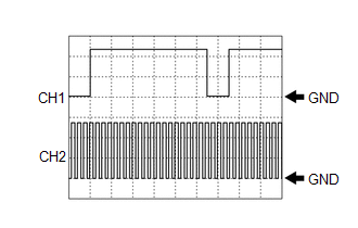
HINT:
The duty of the IWP signal and the frequency of the NIWP signal change according to the coolant (for inverter) temperature.
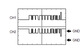
(2) Waveform 2 (MG ECU communication request signal)
|
Item |
Content |
|---|---|
|
Terminal |
CH1: A24-31 (HMCH) - G46-6 (E1) CH2: A24-30 (HMCL) - G46-6 (E1) |
|
Equipment Setting |
1 V/DIV., 50 μs./DIV. |
|
Condition |
Power switch on (IG) |
HINT:
The waveform will vary depending on the content of the digital communication (digital signal).
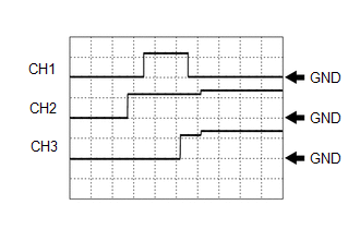
(3) Waveform 3 (System main relay operation signal)
|
Item |
Content |
|---|---|
|
Terminal |
CH1: G46-3 (SMRP) - G46-5 (E01) CH2: G46-4 (SMRB) - G46-5 (E01) CH3: G46-1 (SMRG) - G46-5 (E01) |
|
Equipment Setting |
10 V/DIV., 200 ms./DIV. |
|
Condition |
Power switch on (IG) → Power switch on (READY) |
(4) Waveform 4 (CAN communication signal)
|
Item |
Content |
|---|---|
|
Terminal |
CH1: G46-34 (CA4H) - G46-6 (E1) CH2: G46-35 (CA4L) - G46-6 (E1) |
|
Equipment Setting |
1 V/DIV., 50 μs./DIV. |
|
Condition |
Power switch on (IG) |
HINT:
The waveform will vary depending on the content of the digital communication (digital signal).
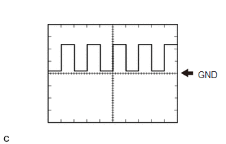
(5) Waveform 5 (Airbag activation signal)
|
Item |
Content |
|---|---|
|
Terminal |
G47-14 (ABFS) - G46-6 (E1) |
|
Equipment Setting |
5 V/DIV., 150 ms./DIV. |
|
Condition |
Power switch on (READY) |
(6) Waveform 6 (CAN communication signal)
|
Item |
Content |
|---|---|
|
Terminal |
CH1: G47-25 (CA1H) - G46-6 (E1) CH2: G47-24 (CA1L) - G46-6 (E1) |
|
Equipment Setting |
1 V/DIV., 50 μs./DIV. |
|
Condition |
Power switch on (IG) |
HINT:
The waveform will vary depending on the content of the digital communication (digital signal).

(7) Waveform 7 (CAN communication signal)
|
Item |
Content |
|---|---|
|
Terminal |
CH1: G47-31 (CA3P) - G46-6 (E1) CH2: G47-30 (CA3N) - G46-6 (E1) |
|
Equipment Setting |
1 V/DIV., 50 μs./DIV. |
|
Condition |
Power switch on (IG) |
HINT:
The waveform will vary depending on the content of the digital communication (digital signal).

|
|
|