| 
                     
                        | Last Modified: 08-21-2023 | 6.11:8.1.0 | Doc ID: RM100000001RDNA |  
                        | Model Year Start: 2021 | Model: Avalon | Prod Date Range: [08/2020 -                    
                                       ] |  
                        | Title: POWER ASSIST SYSTEMS: POWER STEERING SYSTEM (for Gasoline Model): Drive Mode Select Switch Circuit; 2021 - 2022 MY Avalon [08/2020 -        ] |  
                     
                        
                           | Drive Mode Select Switch Circuit |  DESCRIPTION
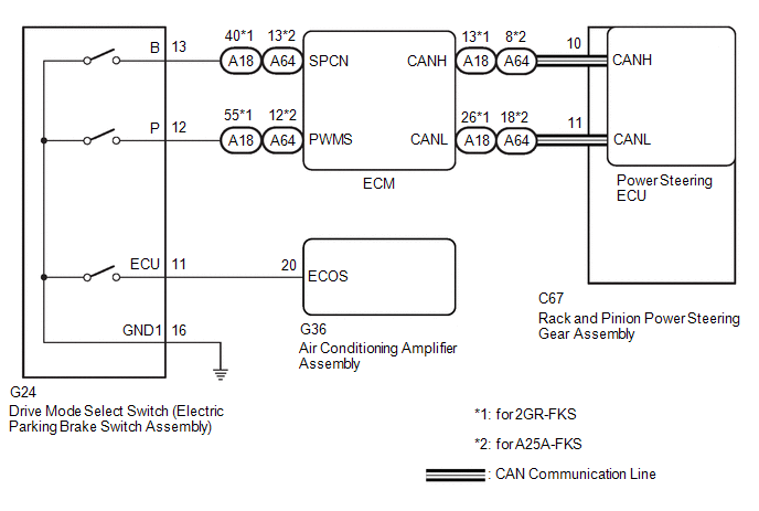
The characteristics of the electronic throttle and EPS operation change according to operation of the drive mode select switch (electric parking brake switch assembly). WIRING DIAGRAM  PROCEDURE
                     
                        
                           | 1.  | CHECK THE PROBLEM SYMPTOMS |  (a) Check each symptom by checking the suspected areas in the table below. 
                     
                        
                           | Result | Proceed to |  
                           | SPORT mode or NORMAL mode is abnormal. | A |  
                           | ECO mode is abnormal. | B |  
                     
                        | 
                              
                                 | A |  
                                 |   |  |  
                     
                        
                           | 2.  | CHECK CAN COMMUNICATION SYSTEM |  (a) Check for DTCs. Click here
                        
                           
                              ![2019 - 2022 MY Avalon [04/2018 -        ]; NETWORKING: CAN COMMUNICATION SYSTEM (for Gasoline Model): HOW TO PROCEED WITH TROUBLESHOOTING](/t3Portal/stylegraphics/info.gif)  
                     
                        
                           | Result | Proceed to |  
                           | CAN communication system DTCs are not output. | A |  
                           | CAN communication system DTCs are output. | B |  
                     
                        | 
                              
                                 | A |  
                                 |   |  |  
                     
                        
                           | 3.  | CHECK HARNESS AND CONNECTOR (DRIVE MODE SELECT SWITCH (ELECTRIC PARKING BRAKE SWITCH ASSEMBLY) - BODY GROUND) |  (a) Turn the engine switch off. 
                     
                        
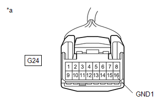
                           | (b) Disconnect the G24 drive mode select switch (electric parking brake switch assembly) connector. | 
                                 
                                    |   |  
                                    | 


                                                | *a | Front view of wire harness connector (to Drive mode select switch (Electric parking brake switch assembly)) |  |  |  (c) Measure the resistance according to the value(s) in the table below. Standard Resistance:  


                           | Tester Connection | Condition | Specified Condition |  
                           | G24-16 (GND1) - Body ground | Always | Below 1 Ω |  
                     
                        
                           | NG |   | REPAIR OR REPLACE HARNESS OR CONNECTOR |  
                     
                        | 
                              
                                 | OK |  
                                 |   |  |  
                     
                        
                           | 4.  | INSPECT DRIVE MODE SELECT SWITCH (ELECTRIC PARKING BRAKE SWITCH ASSEMBLY) |  (a) Inspect drive mode select switch (electric parking brake switch assembly). for UA80E: Click here
                        
                           
                              ![2019 - 2022 MY Avalon [04/2018 -        ]; UA80E (AUTOMATIC TRANSMISSION / TRANSAXLE): COMBINATION SWITCH: INSPECTION](/t3Portal/stylegraphics/info.gif)  for UB80F: Click here
                        
                           
                              ![2021 - 2022 MY Avalon [08/2020 -        ]; UB80F (AUTOMATIC TRANSMISSION / TRANSAXLE): COMBINATION SWITCH: INSPECTION](/t3Portal/stylegraphics/info.gif)  OK:  Drive mode select switch (Electric parking brake switch assembly) is normal. 
                     
                        
                           | Result | Proceed to |  
                           | CAN communication system DTCs are not output. (for 2GR-FKS) | A |  
                           | CAN communication system DTCs are not output. (for A25A-FKS) | B |  
                           | CAN communication system DTCs are output. | C |  
                     
                        
                           | C |   | REPLACE DRIVE MODE SELECT SWITCH (ELECTRIC PARKING BRAKE SWITCH ASSEMBLY)
 for UA80E: Click here
                                       
                                          
                                             ![2019 - 2022 MY Avalon [04/2018 -        ]; UA80E (AUTOMATIC TRANSMISSION / TRANSAXLE): COMBINATION SWITCH: REMOVAL](/t3Portal/stylegraphics/info.gif)  for UB80F: Click here
                                       
                                          
                                             ![2021 - 2022 MY Avalon [08/2020 -        ]; UB80F (AUTOMATIC TRANSMISSION / TRANSAXLE): COMBINATION SWITCH: REMOVAL](/t3Portal/stylegraphics/info.gif)  |  
                     
                        | 
                              
                                 | A |  
                                 |   |  |  
                     
                        
                           | 5.  | CHECK HARNESS AND CONNECTOR (DRIVE MODE SELECT SWITCH (ELECTRIC PARKING BRAKE SWITCH ASSEMBLY) - ECM) |  (a) Connect the G24 drive mode select switch (electric parking brake switch assembly) connector. 
                     
                        
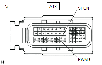
                           | (b) Disconnect the A18 ECM connectors. | 
                                 
                                    |   |  
                                    | 


                                                | *a | Front view of wire harness connector (to ECM) |  |  |  (c) Measure the resistance according to the value(s) in the table below. Standard Resistance:  w/ Adaptive Variable Suspension System


                           | Tester Connection | Condition | Specified Condition |  
                           | A18-55 (PWMS) - Body ground | SPORT S/S+ mode switch being turned and held | Below 1 Ω |  
                           | A18-55 (PWMS) - Body ground | SPORT S/S+ mode switch not turned | 10 kΩ or higher |  
                           | A18-40 (SPCN) - Body ground | NORMAL/CUSTOM mode switch being pushed and held | Below 1 Ω |  
                           | A18-40 (SPCN) - Body ground | NORMAL/CUSTOM mode switch not pushed | 10 kΩ or higher |  w/o Adaptive Variable Suspension System


                           | Tester Connection | Condition | Specified Condition |  
                           | A18-55 (PWMS) - Body ground | SPORT mode switch being turned and held | Below 1 Ω |  
                           | A18-55 (PWMS) - Body ground | SPORT mode switch not turned | 10 kΩ or higher |  
                           | A18-40 (SPCN) - Body ground | NORMAL mode switch being pushed and held | Below 1 Ω |  
                           | A18-40 (SPCN) - Body ground | NORMAL mode switch not pushed | 10 kΩ or higher |  
                     
                        
                           | NG |   | REPAIR OR REPLACE HARNESS OR CONNECTOR |  
                     
                        
                           | 6.  | CHECK HARNESS AND CONNECTOR (DRIVE MODE SELECT SWITCH (ELECTRIC PARKING BRAKE SWITCH ASSEMBLY) - ECM) |  (a) Connect the G24 drive mode select switch (electric parking brake switch assembly) connector. 
                     
                        
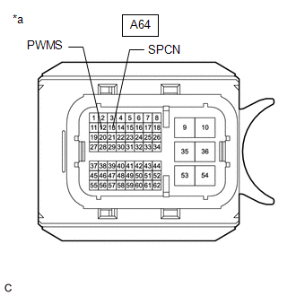
                           | (b) Disconnect the A64 ECM connectors. | 
                                 
                                    |   |  
                                    | 


                                                | *a | Front view of wire harness connector (to ECM) |  |  |  (c) Measure the resistance according to the value(s) in the table below. Standard Resistance:  


                           | Tester Connection | Condition | Specified Condition |  
                           | A64-12 (PWMS) - Body ground | SPORT mode switch being turned and held | Below 1 Ω |  
                           | A64-12 (PWMS) - Body ground | SPORT mode switch not turned | 10 kΩ or higher |  
                           | A64-13 (SPCN) - Body ground | NORMAL mode switch being pushed and held | Below 1 Ω |  
                           | A64-13 (SPCN) - Body ground | NORMAL mode switch not pushed | 10 kΩ or higher |  
                     
                        
                           | NG |   | REPAIR OR REPLACE HARNESS OR CONNECTOR |  |