| Last Modified: 08-21-2023 | 6.11:8.1.0 | Doc ID: RM100000001QM6L |
| Model Year Start: 2021 | Model: Avalon HV | Prod Date Range: [08/2020 - ] |
| Title: LIGHTING (EXT): LIGHTING SYSTEM (for HV Model without Cornering Light): Back-up Light Circuit; 2021 - 2022 MY Avalon HV [08/2020 - ] | ||
|
Back-up Light Circuit |
DESCRIPTION
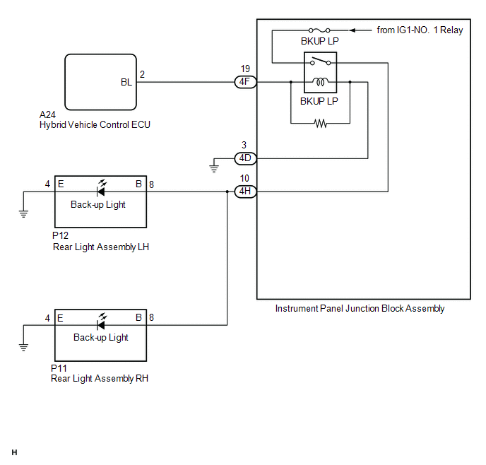
The hybrid vehicle control ECU controls the back-up lights via the BKUP LP relay.
WIRING DIAGRAM
CAUTION / NOTICE / HINT
NOTICE:
- Inspect the fuses for circuits related to this system before performing the following procedure.
-
Before replacing the hybrid vehicle control ECU, refer to Registration.
Click here
![2021 - 2022 MY Avalon HV [08/2020 - ]; THEFT DETERRENT / KEYLESS ENTRY: SMART KEY SYSTEM (for Start Function, HV Model): REGISTRATION](/t3Portal/stylegraphics/info.gif)
PROCEDURE
|
1. |
CHECK FOR DTC |
(a) Connect the Techstream to the DLC3.
(b) Turn the power switch on (IG).
(c) Turn the Techstream on.
(d) Enter the following menus: Powertrain / Hybrid Control / Trouble Codes.
(e) Check for DTCs.
Powertrain > Hybrid Control > Trouble Codes
|
Result |
Proceed to |
|---|---|
|
Hybrid control system DTCs are not output |
A |
|
Hybrid control system DTCs are output |
B |
| B |

|
GO TO HYBRID CONTROL SYSTEM
|
|

|
2. |
CHECK HARNESS AND CONNECTOR (INSTRUMENT PANEL JUNCTION BLOCK ASSEMBLY - BODY GROUND) |
(a) Disconnect the 4D instrument panel junction block assembly connector.
(b) Measure the resistance according to the value(s) in the table below.
Standard Resistance:
|
Tester Connection |
Condition |
Specified Condition |
|---|---|---|
|
4D-3 - Body ground |
Always |
Below 1 Ω |
| NG |
|
REPAIR OR REPLACE HARNESS OR CONNECTOR |
|
|
3. |
CHECK HARNESS AND CONNECTOR (HYBRID VEHICLE CONTROL ECU - INSTRUMENT PANEL JUNCTION BLOCK ASSEMBLY) |
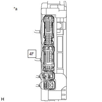
(a) Disconnect the 4F instrument panel junction block assembly connector.
(b) Disconnect the A24 hybrid vehicle control ECU connector.
(c) Measure the resistance according to the value(s) in the table below.
Standard Resistance:
|
Tester Connection |
Condition |
Specified Condition |
|---|---|---|
|
A24-2 (BL) - 4F-19 |
Always |
Below 1 Ω |
|
A24-2 (BL) or 4F-19 - Body ground |
Always |
10 kΩ or higher |
| NG |
|
REPAIR OR REPLACE HARNESS OR CONNECTOR |
|
|
4. |
CHECK HYBRID VEHICLE CONTROL ECU (OUTPUT VOLTAGE) |
|
*a |
Component with harness connected (Instrument Panel Junction Block Assembly) |
(a) Connect the A24 hybrid vehicle control ECU connector.
(b) Connect the 4D and 4F instrument panel junction block assembly connectors.
(c) Measure the voltage according to the value(s) in the table below.
Standard Voltage:
|
Tester Connection |
Condition |
Specified Condition |
|---|---|---|
|
4F-19 - Body ground |
Power switch off, reverse (R) not selected |
Below 1 V |
|
4F-19 - Body ground |
Power switch on (IG), reverse (R) selected |
11 to 14 V |
| NG |
|
REPLACE HYBRID VEHICLE CONTROL ECU
|
|
|
5. |
INSPECT INSTRUMENT PANEL JUNCTION BLOCK ASSEMBLY (OUTPUT VOLTAGE) |
|
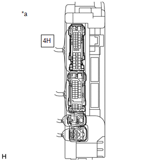
*a |
Component with harness connected (Instrument Panel Junction Block Assembly) |
(a) Measure the voltage according to the value(s) in the table below.
Standard Voltage:
|
Tester Connection |
Condition |
Specified Condition |
|---|---|---|
|
4H-10 - Body ground |
Power switch off, reverse (R) not selected |
Below 1 V |
|
4H-10 - Body ground |
Power switch on (IG), reverse (R) selected |
11 to 14 V |
| OK |
|
REPAIR OR REPLACE HARNESS OR CONNECTOR |
| NG |
|
REPLACE INSTRUMENT PANEL JUNCTION BLOCK ASSEMBLY
|
|
|
|