| Last Modified: 09-10-2025 | 6.11:8.1.0 | Doc ID: RM100000001PY59 |
| Model Year Start: 2021 | Model: Avalon | Prod Date Range: [08/2020 - ] |
| Title: CELLULAR COMMUNICATION: SAFETY CONNECT SYSTEM: Emergency Call Switch Illumination Circuit; 2021 - 2022 MY Avalon Avalon HV [08/2020 - ] | ||
|
Emergency Call Switch Illumination Circuit |
WIRING DIAGRAM
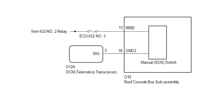
w/ Sliding Roof
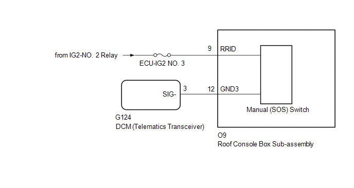
w/o Sliding Roof
CAUTION / NOTICE / HINT
NOTICE:
-
Depending on the parts that are replaced during vehicle inspection or maintenance, performing initialization, registration or calibration may be needed. Refer to Precaution for Safety Connect System.
Click here
![2021 MY Avalon Avalon HV [08/2020 - 08/2021]; CELLULAR COMMUNICATION: SAFETY CONNECT SYSTEM: PRECAUTION](/t3Portal/stylegraphics/info.gif)
- Inspect the fuses for circuits related to this system before performing the following procedure.
PROCEDURE
PROCEDURE
|
1. |
CONFIRM MODEL |
(a) Choose the model to be inspected.
|
Result |
Proceed to |
|---|---|
|
w/ Sliding Roof |
A |
|
w/o Sliding Roof |
B |
| B |

|
|

|
2. |
CHECK HARNESS AND CONNECTOR (ROOF CONSOLE BOX SUB-ASSEMBLY (MANUAL (SOS) SWITCH) POWER SOURCE) |
(a) Disconnect the G124 DCM (telematics transceiver) connector.
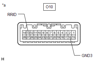
(b) Disconnect the O10 roof console box sub-assembly (manual (SOS) switch) connector.
(c) Measure the voltage according to the value(s) in the table below.
Standard Voltage:
|
Tester Connection |
Switch Condition |
Specified Condition |
|---|---|---|
|
O10-13 (RRID) - Body Ground |
Ignition switch ON |
11 to 14 V |
(d) Measure the resistance according to the value(s) in the table below.
Standard Resistance:
|
Tester Connection |
Condition |
Specified Condition |
|---|---|---|
|
G124-3 (SIG-) - O10-16 (GND3) |
Always |
Below 1 Ω |
|
G124-3 (SIG-) or O10-16 (GND3) - Body ground |
Always |
10 kΩ or higher |
| NG |
|
REPAIR OR REPLACE HARNESS OR CONNECTOR |
|
|
3. |
INSPECT ROOF CONSOLE BOX SUB-ASSEMBLY (MANUAL (SOS) SWITCH) |
|
(a) Remove the roof console box sub-assembly (manual (SOS) switch). Click here
|
|
(b) Apply auxiliary battery voltage to the connector and check that the roof console box assembly comes on.
OK:
|
Measurement Condition |
Condition |
Specified Condition |
|---|---|---|
|
Auxiliary battery positive (+) → O10-13 (RRID) Auxiliary battery negative (-) → O10-16 (GND3) |
Always |
Manual (SOS) switch illumination illuminates |
| OK |
|
| NG |
|
|
4. |
CHECK HARNESS AND CONNECTOR (ROOF CONSOLE BOX SUB-ASSEMBLY (MANUAL (SOS) SWITCH) POWER SOURCE) |
(a) Disconnect the G124 DCM (telematics transceiver) connector.
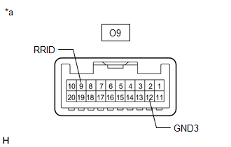
(b) Disconnect the O9 roof console box sub-assembly (manual (SOS) switch) connector.
(c) Measure the voltage according to the value(s) in the table below.
Standard Voltage:
|
Tester Connection |
Switch Condition |
Specified Condition |
|---|---|---|
|
O9-9 (RRID) - Body Ground |
Ignition switch ON |
11 to 14 V |
(d) Measure the resistance according to the value(s) in the table below.
Standard Resistance:
|
Tester Connection |
Condition |
Specified Condition |
|---|---|---|
|
G124-3 (SIG-) - O9-12 (GND3) |
Always |
Below 1 Ω |
|
G124-3 (SIG-) or O9-12 (GND3) - Body ground |
Always |
10 kΩ or higher |
| NG |
|
REPAIR OR REPLACE HARNESS OR CONNECTOR |
|
|
5. |
INSPECT ROOF CONSOLE BOX SUB-ASSEMBLY (MANUAL (SOS) SWITCH) |
|
(a) Remove the roof console box sub-assembly (manual (SOS) switch). Click here
|
|
(b) Apply auxiliary battery voltage to the connector and check that the roof console box assembly comes on.
OK:
|
Measurement Condition |
Condition |
Specified Condition |
|---|---|---|
|
Auxiliary battery positive (+) → O9-9 (RRID) Auxiliary battery negative (-) → O9-13 (GND3) |
Always |
Manual (SOS) switch illumination illuminates |
| NG |
|
|
|
6. |
REPLACE DCM (TELEMATICS TRANSCEIVER) |
(a) Replace the DCM (telematics transceiver) with a new one.
Click here
NOTICE:
- The ignition switch must be off.
- Do not exchange the DCM (telematics transceiver) with one from another vehicle.
| NEXT |
|
|
|
|